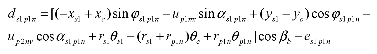
Take the direction shown in the figure as the positive direction, φ S1 is the angle between the connecting line between the center of the planetary gear and the center of the small sun gear and the positive direction of the coordinate axis X, α S1p1n is the meshing angle and defines the relative meshing angle φ s1p1n:
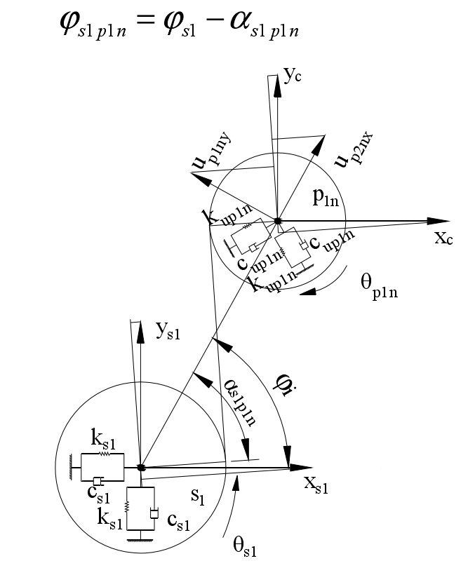
The projection of the linear displacement xs1 and ys1 of the small sun gear S1 on the meshing line is – xs1sin respectively φ s1p1ncos β b、ys1cos φ s1p1ncos β b. The projection of the linear displacement XC and YC of planet carrier C on the meshing line is xcsin respectively φ s1p1ncos β b、-yccos φ s1p1ncos β b. The projection of the linear displacement up1nx and up1ny of the large planetary gear p1n on the meshing line is – up1nxsin respectively φ s1p1ncos β b、-up1nycos φ s1p1ncos β b. Under the pure torsion analysis model, the relative meshing displacement between the small sun gear S1 and the large planet gear p1n is [RS1] θ s1-(rs1+rp1n) θ c+ rp1n θ p1n]cos β B-es1p1n, so under the translation torsion analysis model, the relative displacement ds1p1n between the small sun gear S1 and the large planet gear p1n: