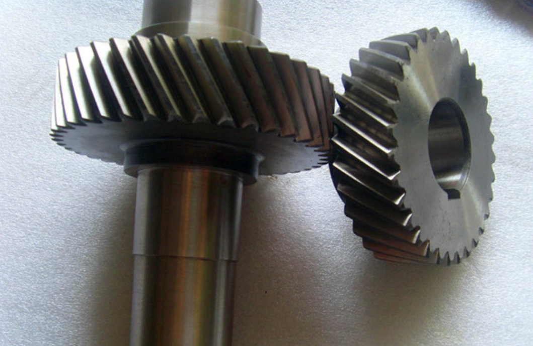
With the increasing demands for energy efficiency in electric vehicles, helical gears have become critical components in powertrain systems due to their smooth transmission characteristics. This study investigates the simulation reliability of modified helical gears under varying rotational speeds by analyzing mesh sensitivity, contact stress distribution, and transmission error characteristics.

1. Fundamental Theoretical Framework
The dynamic behavior of helical gears can be modeled using the multi-degree-of-freedom system:
$$ M\ddot{q} + C\dot{q} + K(q – e) = F $$
Where \( M \) represents the mass matrix, \( C \) the damping matrix, \( K \) the time-varying stiffness matrix, and \( F \) the external load vector. For helical gear pairs, the contact stress follows the modified Hertzian formulation:
$$ \sigma_H = \sqrt{\frac{F_t}{\pi} \left( \frac{1-\nu_1^2}{E_1} + \frac{1-\nu_2^2}{E_2} \right) \frac{1}{\beta_\Sigma} } $$
2. Mesh Sensitivity Analysis
The helical gear pair parameters and operating conditions are summarized below:
| Parameter | Pinion | Gear |
|---|---|---|
| Number of Teeth | 23 | 93 |
| Normal Module (mm) | 1.93 | |
| Pressure Angle (°) | 16.0 | |
| Helix Angle (°) | 25.6 | |
| Face Width (mm) | 42.0 | 46.5 |
Mesh convergence analysis reveals distinct patterns for different speed regimes:
| Direction | Critical Mesh Count | Stress Variation (MPa) | Transmission Error (μm) |
|---|---|---|---|
| Involute | >15 | <0.8 | <0.003 |
| Face Width | 110 | 4.1 → 0.4 | 0.0065 → 0.0007 |
The helical gear’s transmission error demonstrates strong correlation with mesh density along the face width:
$$ TE = \phi_1 r_{b1} – \phi_2 r_{b2} $$
Where \( \phi \) represents angular displacement and \( r_b \) denotes base circle radius.
3. Speed-Dependent Behavior
Comparative analysis of high-speed (20,000 rpm) and low-speed (3,500 rpm) conditions shows:
| Performance Metric | High Speed Sensitivity | Low Speed Sensitivity |
|---|---|---|
| Max Contact Stress | 4.1 MPa variation | 24.0 MPa variation |
| PPT Error | 0.0065 μm variation | 0.0940 μm variation |
| Mesh Saturation | 120 elements | 110 elements |
The contact pattern evolution follows the relationship:
$$ \beta_\Sigma = \frac{1}{\frac{1}{\rho_1} + \frac{1}{\rho_2}} $$
Where \( \rho \) denotes curvature radius at contact points.
4. Optimization Strategy
Recommended mesh parameters for reliable helical gear simulation:
| Simulation Aspect | Involute Direction | Face Width Direction |
|---|---|---|
| Stress Analysis | 20-25 elements | 110-120 elements |
| Error Prediction | 15-20 elements | 100-110 elements |
| Contact Pattern | 18-22 elements | 80-90 elements |
This study confirms that helical gear simulations require different mesh strategies for high-speed and low-speed conditions. The face width direction consistently demonstrates higher mesh sensitivity compared to involute direction, particularly in low-speed torque-dominant operations.
