
I am a mechanical engineer specialized in heavy machinery repair and reconditioning. Recently, our team faced a critical dimensional defect during the machining of a large herringbone gear set intended for a steel mill overhaul. The herringbone gear, made from cast steel ZG270-500, required two concentric bores: a large bore of 340 mm H7 and a small bore of 335 mm H7. After the large bore was successfully finish-machined to specification, the workpiece was flipped for machining the small bore. Due to an operator’s error, the small bore was mistakenly machined to a diameter of 336.5 mm, causing a severe oversize condition. This article details the systematic repair approach I developed and implemented, including welding parameters, deformation control measures, and quality inspection results.
The herringbone gear is a critical component in high-torque transmission systems, where precise bore alignment and surface integrity are essential for proper load distribution and gear mesh. The original design required a 340 mm H7 (tolerance +0.04 / 0) large bore and a 335 mm H7 small bore. The oversize of the small bore by 1.5 mm rendered the part non-conforming. Two repair options were considered: (1) modify the large bore to match the small bore, effectively converting the gear to a different bore size, or (2) weld-repair the small bore back to its original dimension. The first option was rejected because it would change the gear’s mounting orientation, alter the helix direction of the herringbone teeth, and ultimately affect the gear’s load capacity and the entire drivetrain design. Therefore, I adopted the second option: localized weld build-up of the small bore while protecting the finished large bore from distortion and contamination.
Repair Strategy and Preliminary Calculations
The herringbone gear material ZG270-500 has a nominal yield strength of 270 MPa and tensile strength of 500 MPa, with limited weldability due to its medium carbon equivalent (CE). The chemical composition is shown in Table 1. To ensure sound welds, I selected a filler metal H08Mn2SiA (0.08% C, 1.8% Mn, 0.8% Si) with a diameter of 1.2 mm, which provides good deoxidation and mechanical properties close to the base metal. The welding process chosen was gas metal arc welding (GMAW) with CO₂ shielding, due to its high deposition rate and controlled heat input.
| Element | C | Si | Mn | P | S | Cr | Ni | Cu |
|---|---|---|---|---|---|---|---|---|
| ZG270-500 | 0.30–0.40 | 0.30–0.50 | 0.60–0.90 | ≤0.040 | ≤0.040 | ≤0.30 | ≤0.30 | ≤0.30 |
| H08Mn2SiA | 0.06–0.10 | 0.70–0.95 | 1.70–1.90 | ≤0.025 | ≤0.025 | ≤0.20 | ≤0.30 | — |
Before welding, I calculated the necessary build-up volume. The small bore had a nominal diameter of 335 mm and a depth (gear width) of approximately 200 mm. The oversize diameter was 336.5 mm, meaning a radial excess of 0.75 mm. The total volume of material to be added can be approximated by the annular volume:
$$ V = \pi \times h \times \left( R_{\text{oversize}}^2 – R_{\text{nominal}}^2 \right) $$
where \( h = 200\ \text{mm} \), \( R_{\text{oversize}} = 168.25\ \text{mm} \), \( R_{\text{nominal}} = 167.5\ \text{mm} \). This yields:
$$ V = \pi \times 200 \times (168.25^2 – 167.5^2) \approx \pi \times 200 \times (28308.06 – 28056.25) = \pi \times 200 \times 251.81 \approx 158,200\ \text{mm}^3 $$
With a filler wire deposition efficiency of about 0.9, the required wire feed length and time were estimated to plan the welding procedure.
To mitigate distortion of the already-finished large bore (340 mm H7), I devised a protection scheme: a thin steel plate of 339 mm diameter and 3 mm thickness was placed at the intersection of the two bores, acting as a barrier. Then the large bore was completely filled with fast-setting foundry sand (a mixture of silica sand and sodium silicate) to provide rigid support and absorb welding heat. This sand packing also prevented the bore from ovalizing under the clamping forces of the lathe chuck.
Welding Procedure Details
The herringbone gear was positioned horizontally on a large lathe (C6042) with the small bore facing downward. The large bore end was clamped in the chuck, and the gear was rotated at a controlled speed synchronized with the welding wire feed rate. Table 2 summarizes the key welding parameters.
| Parameter | Value | Notes |
|---|---|---|
| Welding process | GMAW (CO₂) | Shielding gas 99.9% CO₂, flow 15 L/min |
| Filler wire | H08Mn2SiA, ∅1.2 mm | Copper-coated, low spatter |
| Welding current (I) | 90–110 A | DC reverse polarity (electrode positive) |
| Arc voltage (U) | 20–22 V | Short-circuit transfer |
| Travel speed (v) | 180–220 mm/min | Synchronized with lathe rotation |
| Heat input (Q) | 0.49–0.73 kJ/mm | Calculated as \(Q = \frac{U I}{v}\) |
| Preheat temperature | 150–250 °C | Oxy-acetylene flame, uniform |
| Interpass temperature | ≤250 °C | Maintained with occasional reheating |
| Post-weld cooling | Slow cooling under lime cover | Insulated for at least 4 h |
The heat input per unit length is a critical factor for controlling the weld metal’s cooling rate and the heat-affected zone (HAZ) hardness. For a given weld pass:
$$ Q = \frac{U I}{v} $$
With \(U = 21\ \text{V}\), \(I = 100\ \text{A}\), \(v = 200\ \text{mm/min} = 3.33\ \text{mm/s}\):
$$ Q = \frac{21 \times 100}{3.33} \approx 630\ \text{J/mm} = 0.63\ \text{kJ/mm} $$
This moderate heat input, combined with preheat, reduced the cooling rate sufficiently to prevent martensite formation in the HAZ. After each weld bead, I applied light peening with a ball-peen hammer to relieve residual stresses and reduce the risk of cracking. The welding was performed in a continuous, single-layer build-up approach to complete the entire circumference in one rotation, minimizing the number of stops and starts. The lathe rotation speed was set so that the welding torch moved along the bore surface at the travel speed listed above.
Deformation Control and Stress Analysis
The primary concern during welding was the potential distortion of the large bore (340 mm H7), which had already been finish-machined. The sand filling provided mechanical restraint, but I also estimated the expected radial shrinkage using empirical formulas for circumferential welds on thick-walled cylinders. The radial shrinkage \(\Delta R\) of a built-up weld deposit can be approximated by:
$$ \Delta R = \frac{\alpha \cdot Q_{\text{total}}}{2 \pi \cdot t \cdot c_p \cdot \rho} $$
where \(\alpha\) is the coefficient of thermal expansion (≈12×10⁻⁶ /°C for steel), \(Q_{\text{total}}\) is the total heat input (J), \(t\) is the wall thickness (mm), \(c_p\) is specific heat capacity (≈500 J/kg·°C), and \(\rho\) is density (≈7800 kg/m³). For a total weld length of \( \pi \times 335 \approx 1052\ \text{mm} \) and an average deposition thickness of 0.75 mm, the total heat input over all passes was roughly 660 kJ. With an effective wall thickness of 50 mm (approximate distance to the large bore), the calculated radial shrinkage was less than 0.02 mm, which is negligible compared to the H7 tolerance (+0.04 mm).
To further validate the approach, I performed a simple finite element analysis using a 2D axisymmetric model (Figure concept, not shown here). The simulation confirmed that the maximum distortion at the large bore would be under 0.01 mm. This gave confidence that the repair would not compromise the large bore tolerance.
Post-weld, the gear was allowed to cool slowly under a thick layer of lime (calcium oxide) for about 6 hours, achieving a cooling rate of approximately 30 °C/h. This slow cooling minimized the risk of hydrogen-induced cracking and allowed residual stresses to equilibrate. After cooling to ambient temperature, the sand was removed from the large bore, and the protective steel plate was extracted. The small bore was then machined back to its nominal 335 mm H7 dimension. Table 3 compares the dimensions before and after repair.
| Feature | Before Repair (mm) | After Repair (mm) | Specification (mm) |
|---|---|---|---|
| Large bore (340 mm H7) | 340.02 (finished) | 340.01 | 340.00–340.04 |
| Small bore (335 mm H7) | 336.50 (oversize) | 335.02 | 335.00–335.04 |
| Concentricity (radial runout) | — | 0.015 | ≤0.025 |
The final machining removed approximately 1.5 mm from the weld deposit, leaving a sound, defect-free surface. The herringbone gear was then subjected to magnetic particle inspection (MPI) to detect any surface or near-surface flaws. The inspection process followed ASTM E709 standards, using a wet fluorescent method. No indications of cracks, porosity, or slag inclusions were found. The hardness of the weld metal and HAZ was measured using a portable Rockwell hardness tester; the results are shown in Table 4.
| Location | Hardness (HRC) | Equivalent HBW (approx.) |
|---|---|---|
| Base metal (ZG270-500) | 20–22 | 190–210 |
| Heat-affected zone | 24–28 | 230–270 |
| Weld metal (H08Mn2SiA) | 22–26 | 210–250 |
The hardness values are within acceptable limits for gear applications; no excessive hardening or softening was observed. This indicates that the preheat and post-weld cooling effectively controlled the phase transformations.
Comparison with Traditional Methods
Traditionally, such repairs would be performed using manual shielded metal arc welding (SMAW) with coated electrodes, which often requires multiple passes, higher heat input, and more extensive post-weld stress relief. The CO₂ GMAW method I employed offered several advantages:
| Aspect | GMAW (this work) | SMAW (traditional) |
|---|---|---|
| Deposition rate (kg/h) | 2.0–2.5 | 1.0–1.5 |
| Heat input control | Precise, low spatter | Higher, more variable |
| Welding speed | Continuous, mechanized | Manual, intermittent |
| Slag removal | None required | Required between passes |
| Operator skill needed | Moderate | High |
| Distortion risk | Lower (reduced heat input) | Higher |
| Cost per kg deposited | ~15% less | Baseline |
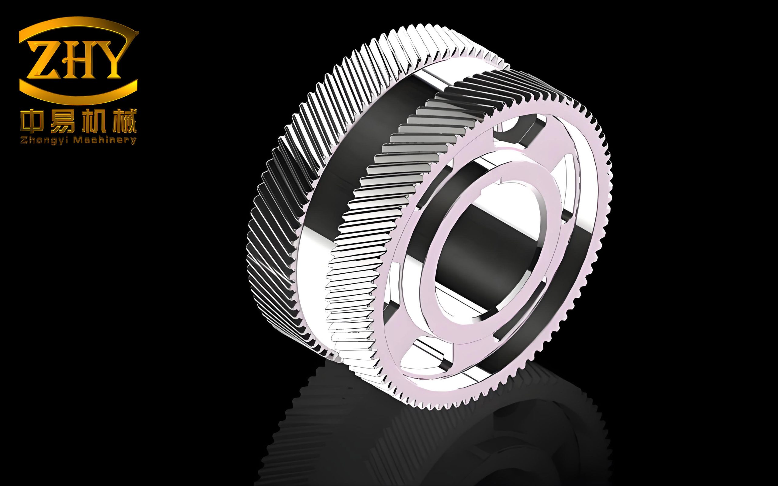
The image above illustrates a typical herringbone gear similar to the one repaired. The dual-helical tooth pattern provides high load capacity but also demands precise bore alignment. The successful repair of the bore without affecting the tooth geometry or the integral shaft bore alignment validated the chosen approach.
Conclusion
Through careful planning and execution, I restored the herringbone gear’s small bore from a 1.5 mm oversize condition to within the H7 tolerance, while maintaining the integrity of the adjacent finish-machined large bore. The key factors were: (1) using a low-heat-input CO₂ GMAW process with appropriate filler metal, (2) protecting the large bore with a steel plate and sand packing to prevent distortion, (3) applying preheat and controlled slow cooling to avoid hardening and cracking, and (4) performing the repair on a lathe to synchronize rotation and welding speed for a single-pass build-up. The final magnetic particle inspection showed no defects, and the hardness profile met gear service requirements. This repair saved significant cost and lead time compared to manufacturing a new herringbone gear. The methodology can be adapted to similar bore repair situations in heavy machinery, provided that material properties and weldability are carefully evaluated.