
Abstract: The processing principles of arc tooth bevel gears, the necessary movements of the machine tool, and designs the transmission schematic diagram of the machine tool. It adopts a three-axis CNC system for control, combining the advantages of mechanical transmission and CNC system control. This avoids the problems of complex machine tool structure, numerous adjustment parameters, and difficulties in maintenance and repair caused by relying solely on mechanical transmission. At the same time, it avoids the issues of many CNC axes and difficult programming brought by relying solely on CNC system driving.
Keywords: CNC; Arc tooth; Bevel gear; Gear milling; Gear grinding; Machine tool
1. Introduction
Bevel gears with arc teeth are a type of spiral bevel gears, where the tooth pitch line is part of an arc. During the meshing process of the gear pair, the teeth gradually and smoothly enter the mesh from one end to the other. At the same time, multiple teeth are in mesh, and compared with straight bevel gears, arc tooth bevel gears have advantages such as a larger overlap coefficient, lower tooth surface pressure, smoother transmission, lower impact and noise, higher load capacity, and longer lifespan. Therefore, arc tooth bevel gears are widely used in transmitting motion between intersecting axes, especially in industries such as automobiles, airplanes, machine tools, petroleum, chemicals, metallurgy, and mining machinery.
Due to the complexity of tooth structure, processing methods, and gear installation structures, traditional mechanically structured machine tools have numerous adjustment parameters, are time-consuming and labor-intensive, and difficult to ensure quality. Most existing CNC arc tooth bevel gear processing machine tools domestically and internationally use five-axis or six-axis CNC systems, which are costly and complex to program, maintain, and repair.
This paper replaces the complex mechanical structure with a three-axis CNC system while retaining simple mechanical structure adjustments, making the machine tool simple in structure, low in cost, and convenient to operate and maintain. At the same time, it combines gear milling and grinding, expanding the functionality of the machine tool, improving the process range, and reducing enterprise purchase costs.
2. Processing Principles of Arc Tooth Bevel Gears
The generation method for processing arc tooth bevel gears is based on a hypothetical gear meshing with the workpiece gear for tooth cutting. The rocking table mechanism on the processing machine tool simulates a hypothetical gear, and the cutting surface of the cutter head mounted on the rocking table is a tooth of the hypothetical gear. When the gear to be processed and the hypothetical gear mesh with each other at a certain transmission ratio, the cutter head cuts a tooth space on the workpiece blank. The cutting surface of the cutter head and the machined tooth surface of the gear are a pair of completely conjugate tooth surfaces. This hypothetical gear is called a铲形轮 (shovel-shaped gear), and its tooth surface is replaced by the trajectory surface of the cutting edge of the cutter head on the machine tool’s rocking table relative to the motion of the rocking table. The shovel-shaped gear can be a plane gear or a flat-top gear, corresponding to two different processing methods.
| Type of Gear | Characteristics | Advantages and Disadvantages |
|---|---|---|
| Plane Gear | Semi-cone angle δ₂/₂ = 90°, the pitch cone surface is a circular plane centered at the cone apex. | Easy to manufacture tools with high precision. However, the machine structure is complex due to the changing tool path with different tooth apex angles. |
| Flat-top Gear | Pitch cone angle δ₂/₂ = 90 – θα (θα is the tooth apex angle), and the top cone surface is a circular plane. | The tool path does not need to be changed for different tooth apex angles, resulting in a simpler machine structure. |
3. Working Principle
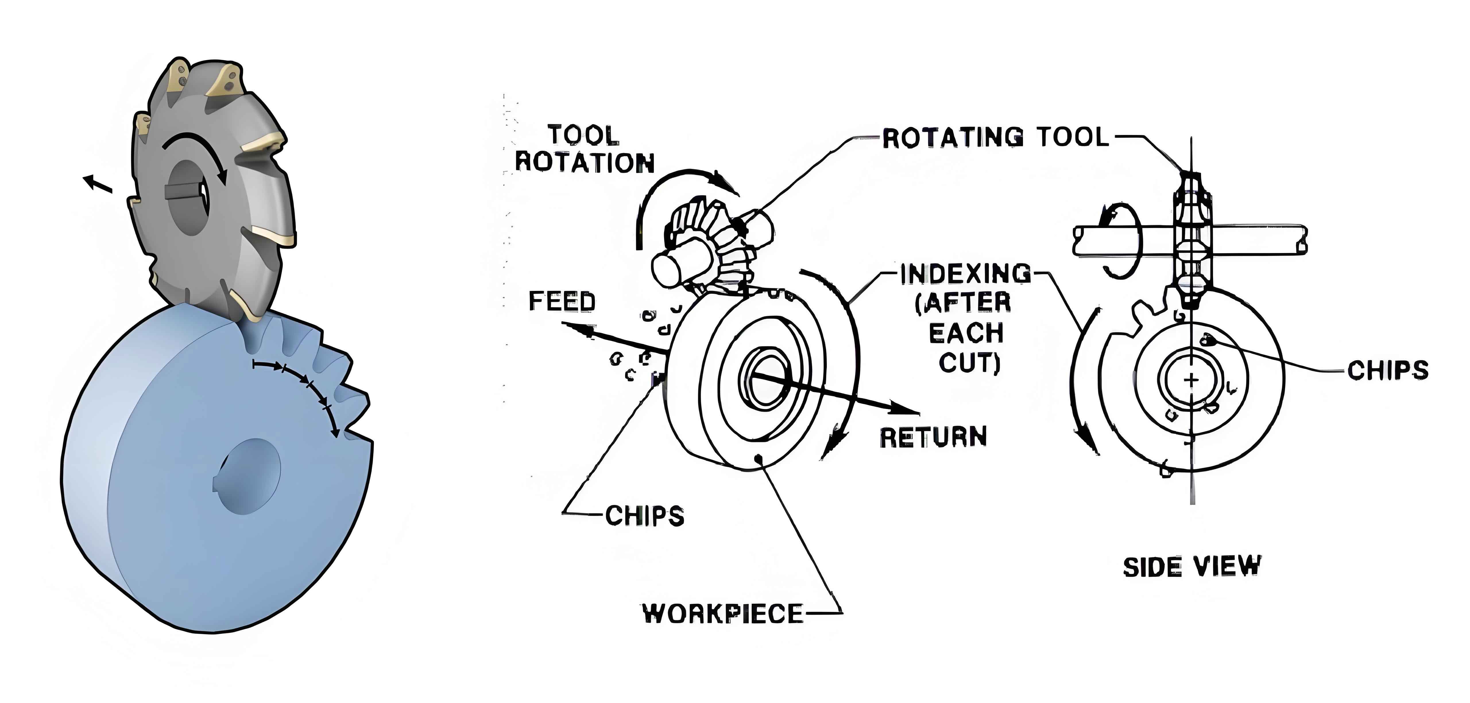
The processing principle of arc tooth bevel gears uses a hypothetical flat-top gear formed during tool movement to process the tooth profile of the workpiece during rolling with the workpiece. The tool used is a milling cutter head. Tthe cutting teeth of the milling cutter head 4 are staggered to form inner and outer rows of cutting edges. In fact, the hypothetical flat-top gear 2 only exists as a single tooth formed by the rotation of the milling cutter head. When the tool rocking table 1 rotates slowly around the center, a segment of the movement trajectory of the cutting teeth of the milling cutter head forms a tooth profile of the shovel-shaped gear. During the generation motion of the shovel-shaped gear and the workpiece 3, the two sides of the involute tooth profile of a tooth space are cut out on the workpiece.
In a working cycle of the arc tooth milling machine, only one tooth space of the workpiece can be processed. After each tooth space is processed, the tool needs to be withdrawn from the workpiece and indexed once, gradually processing all the teeth.
4. Movement Analysis of the Machine Tool
Based on the above analysis, the following movements are required for the arc tooth bevel gear milling machine:
| Movement Type | Description |
|---|---|
| Main Movement | The rotational motion of the milling cutter head to cut the tooth space on the workpiece blank. |
| Generation Motion | The simulated working transmission between the cutting tool (cutter head) and the workpiece to maintain a determined speed ratio relationship. |
| Feed Motion | Continuously feeding the layer to be cut into the cutting to gradually cut out the entire surface. (Also the generation motion for this machine tool.) |
| Cutting-in Motion | The tool cuts into the workpiece to a certain depth to ensure the required size of the workpiece. |
| Indexing Motion | Periodic displacement and conversion of multi-station worktables, tool posts, etc., to sequentially process each surface of the workpiece or use different tools. |
| Positioning Motion | To position the tool and workpiece correctly. This movement can be operated manually. |
5. Transmission Principle of the Machine Tool
Based on the traditional mechanically transmitted arc tooth bevel gear milling machine, simple transmissions are retained, and complex transmissions and machine tool adjustments are realized using a CNC system. This solution can be implemented using a three-axis linked CNC system.
- Main Movement: The main motion motor is an AC variable frequency motor, and a set of fixed gear transmission chains is used. The required cutting speed is obtained through the AC variable frequency motor. To change the cutting speed, only the speed of the variable frequency motor needs to be changed using the CNC system.
- Feed Motion and Generation Motion: Controlled by C-axis servo motor 3 and A-axis servo motor 6, respectively. Motor 6 drives the workpiece to make a slow feed motion through a worm gear, and a pulse encoder is installed at the end of its axis to detect the actual angle turned and feedback to the CNC system. The CNC system controls the rotation of motor 3 to strictly follow the given transmission ratio.
- Cutting-in Motion: Realized by Z-axis motor 7 driving a screw through a fixed gear transmission to move the bed saddle.
- Indexing Motion: Realized by A-axis servo motor 6 driving a worm gear and worm wheel to rotate the workpiece for indexing.
- Positioning Motion: Manually adjust the relative position of the workpiece headstock, bed saddle, and spindle to meet the angle requirement between the workpiece axis and the spindle axis.
6. Machine Tool Structure
It is a schematic diagram of the machine tool’s appearance.
- Spindle Box: Contains the main motor and drives the milling cutter head.
- Tool Rocking Table: Supports the milling cutter head and provides the necessary movement for tool cutting.
- Milling Cutter Head: The tool used for milling (and grinding when replaced with a grinding wheel).
- Workpiece: Mounted on the workpiece headstock.
- Workpiece Headstock: Adjustable on the bed saddle to change the angle.
- Bed Saddle: Provides cutting-in and feed motion.
7. Realization of Gear Grinding
A suitable sheet-like or bowl-shaped grinding wheel is selected and shaped as required. Installing it in the position of the milling cutter head enables the grinding function. This achieves multi-purpose use of one machine, expanding the process range and reducing enterprise equipment purchase costs.
8. Conclusion
The technical solution combines the advantages of mechanical transmission and CNC system control, avoiding the problems of complex machine tool structure, numerous adjustment parameters, and difficulties in maintenance and repair caused by relying solely on mechanical transmission.