
In the modern product development environment, the traditional design paradigm—characterized by fixed organizational structures, centralized resources, and regionally oriented product focus—struggles to meet the demands of rapid market response. The design and manufacturing of mechanical products now require a networked, collaborative approach that enables resource sharing, parallel execution, and agility. Among various mechanical components, worm gears are widely used for transmitting motion and power between non-intersecting shafts, typically at a 90° angle. Their advantages include high transmission ratios, smooth and quiet operation, compact structure, and self-locking capability. However, the design of worm gears is a complex, iterative process involving extensive manual retrieval of tables, charts, and empirical data, leading to long design cycles and low efficiency. To address these challenges, we have developed a web-based worm gear design system that leverages ASP (Active Server Pages), COM (Component Object Model) components, and network database technologies. This system enables rapid, parameterized design of worm gears within a local area network (LAN) or over the Internet, significantly improving design efficiency and facilitating resource sharing among distributed teams.
In this paper, we present the architecture, key technologies, and implementation of the proposed system. We focus on the detailed design process of worm gears, including geometric parameter calculations, strength verification, material selection, and tolerance specification. Multiple comprehensive tables and mathematical formulas are provided to summarize the essential design equations and data. The system has been validated through a practical example, demonstrating its effectiveness and reliability for networked mechanical design.
System Architecture for Resource Sharing
The proposed system adopts a three-tier Browser/Server (B/S) architecture, as illustrated conceptually in Figure 1 (not shown by number). In this architecture, clients access the web server through standard web browsers. The web server handles user requests, executes applications, queries the database, and returns results as HTML pages. This separates the presentation layer, business logic layer, and data layer, enabling scalability, security, and ease of maintenance.
The resource sharing environment includes all design information such as design standards, standard part data, generic part data, drawings, 2D/3D digital models, raw material information, machining process data, and technical documentation. These resources are stored in various formats across different departments. Our system integrates these heterogeneous resources through a unified web interface, allowing designers to access and share information seamlessly. The architecture supports both intra-enterprise collaboration via Intranet and inter-enterprise collaboration via Internet, forming a virtual product development environment.
Table 1 summarizes the roles and responsibilities of each tier in the B/S model.
| Tier | Component | Function |
|---|---|---|
| Presentation Layer | Web Browser (IE, Chrome, etc.) | User interface for input/output; sends HTTP requests; renders HTML pages. |
| Business Logic Layer | Web Server (IIS) + ASP + COM components | Processes user requests; executes ASP scripts; invokes COM components for worm gear calculations; handles session management. |
| Data Layer | Database Server (SQL Server) | Stores design parameters, material data, tolerance tables, and user accounts; provides data persistence and retrieval. |
This architecture ensures that clients do not need to install any specialized software; only a browser is required. All business logic and data processing are performed on the server side, which simplifies maintenance and upgrades.
Key Technologies
ASP and COM Components
ASP is a server-side scripting environment that allows the creation of dynamic, interactive web pages by embedding scripts (VBScript or JScript) within HTML. When a client requests an ASP page, the web server interprets the script, generates HTML, and sends it to the client. The power of ASP lies in its ability to use COM components, which are binary executables (DLLs or EXEs) that encapsulate business logic and computational tasks. COM components are language-independent and can be efficiently executed on the server side, providing faster performance than interpreted scripts for intensive calculations such as worm gear design.
We developed a custom COM component using Visual Basic 6.0, which performs all worm gear design calculations, including geometric parameter determination, strength checks, and tolerance selection. The component exposes several interfaces (properties and methods) that can be called from ASP scripts. For example, a method CalculateWormGear takes input parameters such as power, input speed, transmission ratio, and material type, and returns a set of computed results. This approach offers the following advantages:
- Binary code protection: source code is not exposed to clients, preserving intellectual property.
- Reusability: the same component can be used in multiple applications or web pages.
- Ease of maintenance: any changes to design logic only require updating the component on the server.
Table 2 compares traditional single-machine design with our ASP/COM-based networked approach.
| Aspect | Traditional Single-Machine | Networked ASP/COM System |
|---|---|---|
| Accessibility | Limited to one workstation | Any client with a browser |
| Resource sharing | Requires file transfer/email | Centralized database, real-time sharing |
| Design speed | Manual table lookup, repeated calculation | Automated calculation, instant results |
| Collaboration | Sequential, high latency | Concurrent, low latency |
| Maintenance | Update each installation separately | Update only server component |
Network Database Technology
Combining web technology with database technology (Web-DB integration) enables dynamic data management. In our system, we use SQL Server as the backend database to store design input parameters, intermediate results, material data tables, tolerance data, and user account information. ASP scripts use ADO (ActiveX Data Objects) to connect to the database, execute SQL queries, and retrieve/update data. This separation of data from business logic allows for better security and scalability. For instance, when a user submits a design request, the input parameters are first stored in the database. Then the COM component reads these parameters, performs calculations, writes results back, and finally the ASP page retrieves the results to display to the user.
Table 3 lists some of the database tables used in the system.
| Table Name | Description | Sample Fields |
|---|---|---|
| WormGearInput | Stores user-entered design parameters | Power, InputSpeed, Ratio, ServiceFactor, Material |
| WormGearOutput | Stores computed geometric parameters | Module, WormPitchDia, WormLeadAngle, GearPitchDia, FaceWidth |
| MaterialTable | Contains material properties for worm and wheel | MaterialName, Hardness, AllowableStress, Density |
| ToleranceTable | Contains tolerance values for worm gear inspections | ModuleRange, Grade, RadialRunout, ToothThicknessDeviation |
Detailed Worm Gear Design Process
Worm gear design involves multiple steps: selection of basic parameters, geometric calculations, strength verification (tooth contact and bending), thermal check, and tolerance specification. In this section, we provide a comprehensive set of formulas and data tables that are implemented in our COM component.
Basic Parameters and Geometry
The primary input parameters include: power \(P\) (kW), input speed \(n_1\) (rpm), transmission ratio \(i = n_1/n_2\), desired service factor \(K_A\), and materials for the worm and worm wheel. The worm is typically made of hardened steel (e.g., 40Cr) while the worm wheel is often made of phosphor bronze (e.g., ZQSn10-1) to reduce friction and wear.
The axial module \(m\) is a key parameter. It can be initially selected based on the center distance \(a\) or from empirical formulas. The worm pitch circle diameter \(d_1\) is related to the module by \(d_1 = q \cdot m\), where \(q\) is the worm diameter coefficient. Recommended values of \(q\) range from 8 to 16, depending on the number of worm threads \(z_1\). The worm lead angle \(\gamma\) is given by:
$$ \tan \gamma = \frac{z_1 \cdot m}{d_1} = \frac{z_1}{q} $$
The worm wheel pitch circle diameter \(d_2\) is:
$$ d_2 = m \cdot z_2 = m \cdot (i \cdot z_1) $$
where \(z_2\) is the number of worm wheel teeth. The center distance \(a\) is:
$$ a = \frac{d_1 + d_2}{2} = \frac{m (q + z_2)}{2} $$
Other essential geometric parameters for the worm and wheel are listed in Table 4.
| Parameter | Worm (Symbol/Formula) | Worm Wheel (Symbol/Formula) |
|---|---|---|
| Addendum | \(h_{a1} = m\) | \(h_{a2} = m\) |
| Dedendum | \(h_{f1} = 1.2m\) | \(h_{f2} = 1.2m\) |
| Tooth height | \(h_1 = 2.2m\) | \(h_2 = 2.2m\) |
| Pitch circle diameter | \(d_1 = q m\) | \(d_2 = m z_2\) |
| Tip diameter | \(d_{a1} = d_1 + 2m\) | \(d_{a2} = d_2 + 2m\) |
| Root diameter | \(d_{f1} = d_1 – 2.4m\) | \(d_{f2} = d_2 – 2.4m\) |
| Face width | — † | \(b_2 \approx 0.75 d_{a1}\) |
| Lead angle | \(\gamma = \arctan(z_1/q)\) | \(\beta = \gamma\) (matching helix angle) |
† Worm face width is typically determined based on the wheel geometry.
Strength Verification
Two critical strength checks are required for worm gears: contact strength (to avoid pitting) and bending strength (to avoid tooth breakage). These calculations use the tangential force on the worm wheel \(F_{t2}\). The torque on the worm wheel \(T_2\) is:
$$ T_2 = \frac{9550 \cdot P \cdot \eta}{n_1 / i} $$
where \(\eta\) is the transmission efficiency (typically 0.7-0.9 for worm gears, depending on lead angle and lubrication). The tangential force is:
$$ F_{t2} = \frac{2 T_2}{d_2} $$
Contact strength: The contact stress \(\sigma_H\) is calculated using the Hertz formula adapted for worm gears:
$$ \sigma_H = Z_E \sqrt{\frac{2 K T_2}{d_1^2 d_2}} $$
where \(Z_E\) is the elasticity factor (depends on materials of worm and wheel; for steel worm and bronze wheel, \(Z_E \approx 160 \sqrt{\text{MPa}}\)), and \(K\) is the load distribution factor (usually 1.0-1.3). The calculated \(\sigma_H\) must be less than the allowable contact stress \([\sigma_H]\) of the worm wheel material.
Bending strength: The bending stress \(\sigma_F\) in the worm wheel teeth is given by:
$$ \sigma_F = \frac{1.5 K F_{t2}}{b_2 m} Y_{Fa} Y_{Sa} $$
where \(Y_{Fa}\) is the tooth form factor (depends on effective tooth number), \(Y_{Sa}\) is the stress correction factor, and \(b_2\) is the face width. The calculated value must satisfy \(\sigma_F \le [\sigma_F]\).
Table 5 summarizes the strength check formulas and typical allowable values for common materials.
| Check Type | Formula | Allowable Stress [MPa] (Bronze wheel, hardened steel worm) |
|---|---|---|
| Contact strength | \(\sigma_H = Z_E \sqrt{\frac{2 K T_2}{d_1^2 d_2}}\) | \([\sigma_H] \approx 200-250\) (for phosphor bronze) |
| Bending strength | \(\sigma_F = \frac{1.5 K F_{t2}}{b_2 m} Y_{Fa} Y_{Sa}\) | \([\sigma_F] \approx 50-80\) (depending on material and heat treatment) |
In addition to strength, thermal check is necessary because worm gears generate significant heat due to sliding friction. The allowable thermal power is determined based on the housing surface area and cooling conditions. The thermal power \(P_t\) is approximated by:
$$ P_t = 0.001 \cdot K_t \cdot A \cdot (\theta_{\max} – \theta_0) $$
where \(K_t\) is the heat transfer coefficient, \(A\) is the surface area of the gearbox, \(\theta_{\max}\) is the maximum allowable oil temperature (typically 80-90°C), and \(\theta_0\) is the ambient temperature. The actual heat generated must be less than the dissipated heat, otherwise forced cooling is required.
Tolerances and Inspection
Worm gear quality is specified according to standards such as GB/T 10085-2018 (China) or ISO 10828. Tolerances include radial runout of the worm and wheel, tooth thickness deviations, and contact pattern. The COM component retrieves tolerance values from the database based on the module and accuracy grade. Table 6 gives an example of tolerance values for Grade 6 worm gears (medium precision).
| Parameter | Symbol | Worm (μm) | Wheel (μm) |
|---|---|---|---|
| Radial runout (pitch circle) | \(F_r\) | 12-20 | 16-25 |
| Tooth thickness deviation | \(E_s\) | -40 to -60 | -50 to -70 |
| Pitch deviation | \(f_{pt}\) | ±8 | ±10 |
| Contact pattern length | — | ≥60% tooth length | ≥60% tooth length |
System Implementation Example
Based on the above design methodology, we implemented a fully functional web application. The system homepage presents a login interface, after which the user selects “Worm Gear Design” from a menu. The input page (Figure 5 in the original paper, but not referenced here) collects the following parameters: required power (kW), input speed (rpm), transmission ratio, service factor, material for worm wheel, and desired accuracy grade. After submission, the ASP script calls the COM component to perform all calculations and strength checks. The results are stored in the database and then displayed in an output page showing geometric parameters, stresses, and tolerances. Additionally, the system can generate a 3D model of the worm gear assembly using SolidWorks on the server side, which can be downloaded by the user in various formats (e.g., STEP, IGES, SAT). A corresponding engineering drawing can also be exported as DXF or DWG.
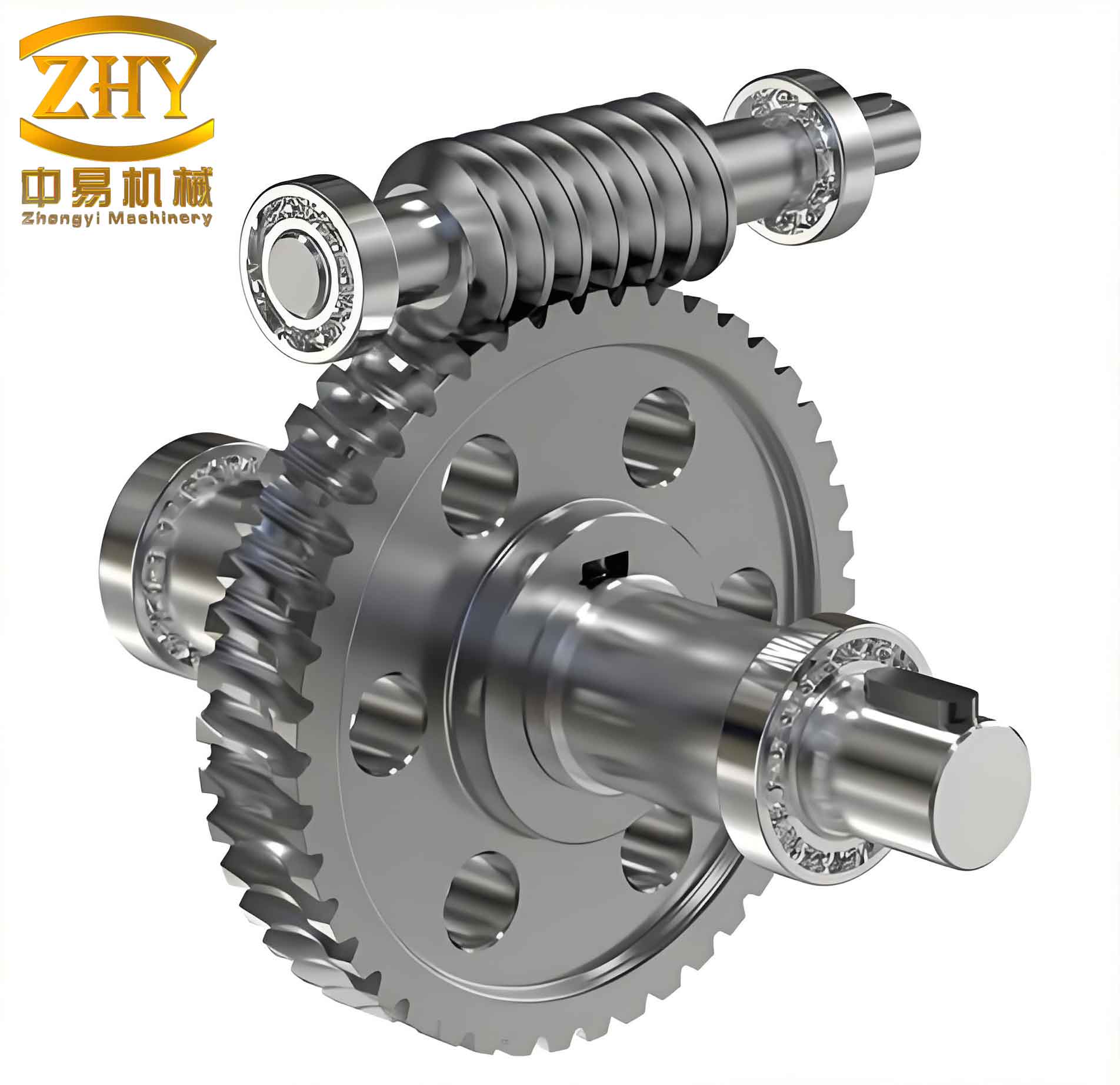
To illustrate the physical geometry of a typical worm gear set, we include a conceptual image below. This image represents a pair of worm and worm wheel with typical tooth forms.
The system has been tested with several design cases. For example, a user requested a worm gear with input power 5.5 kW, input speed 1440 rpm, ratio 20, service factor 1.2, bronze wheel material, and Grade 7 tolerance. The computed results—including module 4 mm, worm pitch diameter 40 mm, wheel pitch diameter 320 mm, contact stress 180 MPa (below allowable 220 MPa), bending stress 45 MPa (below allowable 60 MPa), and thermal power within safe limits—were displayed within seconds. The generated 3D model and 2D drawing were also available for download. The response time was fast due to the compiled COM component, and the web-based interface allowed multiple designers to access the system simultaneously from different locations.
Conclusion
In this work, we have presented a comprehensive study on developing a networked, resource-sharing design system for worm gears using ASP, COM components, and network databases. The system architecture is based on a three-tier B/S model that facilitates easy access and collaboration. The key technologies—ASP for dynamic web content, COM for efficient server-side calculations, and SQL Server for data management—are effectively integrated. The detailed design process of worm gears, including geometric parameter formulas, strength verification equations, material selection, and tolerance tables, has been systematically documented with numerous mathematical formulas and tables.
The implemented system demonstrates significant advantages over traditional single-machine design: reduced design time, elimination of manual table lookup, automated iterative calculations, and the ability for distributed teams to share resources. The inclusion of COM components ensures computational performance and code security. The example test confirms the correctness and efficiency of the system.
Future work may involve extending the system to other types of mechanical transmissions (e.g., helical gears, bevel gears) and incorporating web-based optimization algorithms. Additionally, integrating more interactive features such as real-time 3D visualization using WebGL could further enhance the user experience. The approach presented here provides a viable pattern for the informatization and networking of mechanical product design, especially for complex components like worm gears where iterative calculation and data lookup are prevalent.