
Abstract This article focuses on the research of spiral bevel gear, aiming to explore advanced design and machining methods. It begins with an introduction to the importance of spiral bevel gear in various fields and the challenges faced in their traditional manufacturing processes. The research then delves into the establishment of mathematical models for machining methods based on free – form surface machine tools, with a detailed discussion on gear pair meshing models, including contact attributes and gear side parameters. The article further elaborates on the design of pinion tooth surfaces based on contact attributes, covering aspects such as average contact point rotation angles, first – order and second – order parameters, contact path directions, and parameter corrections. Additionally, it presents a pinion machining method with a fixed workpiece shaft, detailing the determination of tool parameters for both the transmission side and the slip side. Numerical examples and experimental verifications are provided to demonstrate the effectiveness of the proposed methods, including basic parameters, simulation analyses, and rolling tests. The research concludes with a summary of the achievements and potential future research directions.
1. Introduction
Spiral bevel gear play a crucial role in transmitting rotation and torque in aerospace and automotive fields. With the development of numerical control technology, free – form surface machine tools have been widely applied in the design and manufacturing of spiral bevel gear, offering greater design freedom. Previous research has made significant contributions to understanding various aspects of spiral bevel gear, such as root cutting problems, tooth surface modification methods, contact characteristic analyses, and machining mathematical models. This study builds upon these prior efforts and focuses on the active design and manufacturing of face – milling spiral bevel gears using a workpiece shaft – fixed method on a free – form surface machine tool.
2. Gear Pair Meshing Model
2.1 Gear Pair Contact Attributes
The contact attributes of spiral bevel gear pair studied include those for the drive side and the slip side. For the drive side, the contact path’s position and shape, the length of the major axis of the instantaneous contact ellipse at the average contact point, and the transmission error function are considered. For the slip side, the position of the average contact point, the direction of the contact path, the length of the major axis of the instantaneous contact ellipse at the average contact point, and the angular acceleration at the average contact point are included. These attributes can be designed and controlled to achieve specific meshing performance. For example, the contact path on the drive side can be a straight line or a curve in the rotation projection section, and the transmission error can be a quadratic parabola or a higher – order polynomial.
| Contact Side | Contact Attributes |
|---|---|
| Drive Side | Contact path position and shape, major axis length of instantaneous contact ellipse at average contact point, transmission error function |
| Slip Side | Position of average contact point, direction of contact path, major axis length of instantaneous contact ellipse at average contact point, angular acceleration at average contact point |
2.2 Gear Side Parameters
In this study, spiral bevel gear is cut using a forming method with a straight grinding wheel cutting blade. Points on the spatial tooth surface are in one – to – one correspondence with points in the rotation projection coordinates. Given the rotation projection coordinates of any point on spiral bevel gear side, the position vector and unit normal vector of the corresponding point on the spatial tooth surface can be determined, along with the normal curvature and geodesic torsion in any direction from that point. The shape of spiral bevel gear side is determined, and the micro – geometric structure of the pinion side can be actively designed to meet the contact attribute goals.
| Parameter | Description |
|---|---|
| Spatial Tooth Surface Point | In one – to – one correspondence with rotation projection coordinate point |
| Position Vector and Unit Normal Vector | Determined from rotation projection coordinate of gear side point |
| Normal Curvature and Geodesic Torsion | Can be calculated for any direction from the point |
3. Pinion Tooth Surface Design Based on Contact Attributes
3.1 Gear and Pinion Average Contact Point Rotation Angle
During the meshing process, the tooth surface contact points change continuously. When spiral bevel gear and pinion’s average contact points mesh, they rotate around their respective axes by certain angles. The rotation angles satisfy the meshing equation, and based on this, the meshing rotation angle of the average contact point can be calculated. This calculation is crucial for determining the transmission error function.
| Gear and Pinion | Rotation Angle Equation | ||
|---|---|---|---|
| Gear | $\varphi_{W}^{Ref}=2\cdot arctan\left(\frac{U – U\sqrt{U^{2}+V^{2}-W^{2}}/ | U | }{W + V}\right)$ |
| Pinion |
3.2 Pinion Tooth Surface First – Order Parameters
After fully determining the transmission error function and gear side parameters, the first – order parameters of the meshing pinion can be obtained. By taking the magnitude of the pinion angular velocity vector as a reference and using iterative calculations based on the relative velocity equation between spiral bevel gear and pinion, the position vector and unit normal vector of the corresponding point on the pinion side can be calculated for any point on spiral bevel gear side.
| Parameter | Calculation Method |
|---|---|
| Pinion Side Point Position Vector | rF=MppdMpdwMmwr^v |
| Pinion Side Point Unit Normal Vector | nF=MppvMpdwMmwm^v |
3.3 Pinion Tooth Surface Contact Path Direction
For any instantaneous contact point on the pinion contact path, its unit tangent vector along the contact path is consistent with the direction of movement of the given point on the pinion side. By calculating the derivatives of position vectors and using relevant curvature and vector relationships, the unit tangent vector and its perpendicular vector in the tangent plane can be determined.
3.4 Pinion Tooth Surface Second – Order Parameters Correction
At spiral bevel gear average contact point, by considering the normal curvatures and geodesic torsions in different directions and using the defined transmission error function, the second – order parameters of the pinion can be corrected. This correction is important for ensuring accurate meshing performance.
| Parameter | Correction Equation |
|---|---|
| Induced Normal Curvature | rF=MppdMpdwMmwr^v |
| Induced Geodesic Torque | nF=MppvMpdwMmwm^v |
4. Pinion Machining Method with Fixed Workpiece Axis
4.1 Determination of Pinion Transmission Side Tool Parameters
4.1.1 Constraint Equations
The manufacturing of the pinion concave surface aims to ensure the first – order parameters of each point on the contact path (including the average contact point) and the second – order parameters of the average contact point. Additionally, it is necessary to ensure the designed pinion tooth depth during the machining of each point on the contact path. This leads to four independent vector equations as constraints.
| Constraint Equation | Description |
|---|---|
| First Vector Equation | Ensures consistency of pinion side position vector generated by cutter blade with design target |
| Second Vector Equation | Ensures consistency of unit normal vector of pinion side generated by cutter blade with design target |
| Third Vector Equation | Ensures that points generated by tip circle of pinion cutter are on designed pinion root cone |
| Fourth Vector Equation | Ensures that tangent of pinion cutter tip circle is perpendicular to normal vector of designed pinion root cone |
4.1.2 Solving Method
When solving for the machining parameters on spiral bevel gear transmission side, there are 9 independent scalar equations. Given some known parameters such as the pressure angle of the pinion cutter outer blade and the workpiece installation angle, the position coordinates of the pinion cutter center for each point on the contact path can be calculated using elimination and iteration methods.
| Parameter | Known or Calculated |
|---|---|
| Pinion Cutter Outer Blade Pressure Angle | Known |
| Workpiece Installation Angle A | Known |
| Pinion Cutter Center Position Coordinates | Calculated |
4.2 Determination of Pinion Slip Side Tool Parameters
4.2.1 Constraint Equations
The manufacturing of the pinion convex tooth surface aims to first ensure the first – order parameters of the average contact point and then control the second – order parameters through adjustment. This results in two independent vector equations as constraints.
| Constraint Equation | Description |
|---|---|
| First Vector Equation | Ensures consistency of pinion tooth surface position vector generated by cutter blade with design target |
| Second Vector Equation | Ensures consistency of unit normal vector of pinion tooth surface generated by cutter blade with design target |
4.2.2 Solving Method
When solving for the machining parameters on spiral bevel gear side, there are 5 independent scalar equations. Given some known parameters such as the inner blade parameters and the workpiece installation angle, the inner blade radius and pressure angle can be solved using elimination and iteration methods, and the motion curve of the pinion cutter can be determined.
| Parameter | Known or Calculated |
|---|---|
| Inner Blade Parameters and | Known |
| Workpiece Installation Angle A | Known |
| Inner Blade Radius and Pressure Angle | Calculated |
5. Numerical Examples and Experimental Verification
5.1 Basic Parameters
The proposed methods are verified on a face – milling hypoid gear pair of a main reducer. The basic parameters of the gear pair, the preset tool parameters of the grinding wheel, and the preset contact attribute targets are provided.
| Gear Pair Parameter | Pinion | Gear |
| Axis Angle (°) | 90.000 | |
| Spiral Direction | Left | Right |
| Number of Teeth | 7 | 39 |
| Average Spiral Angle (°) | 43.850 | 35.833 |
| Average Pressure Angle (°) | 22.500 | |
| Spiral Angle | 11.883 | 78.000 |
| Outer Diameter (mm) | 212.110 | 217.300 |
| Grinding Wheel Tool Parameter | Outer Blade | Inner Blade |
| Blade Angle (°) | -22.500 | 22.500 |
| Fillet Radius (mm) | 2.290 | 2.290 |
| Tool Radius (mm) | 152.400 | |
| Tip Width (mm) | 5.000 |
| Contact Attribute Target | Transmission Side | Slip Side |
| Average Contact Point Coordinate in Tooth Width Direction h (mm) | 0.000 | 0.000 |
| Average Contact Point Coordinate in Tooth Height Direction i (mm) | 10.650 | 10.650 |
| Contact Path Direction Angle a | 23.000 | |
| Average Contact Point Contact Ellipse Major Axis Length L (mm) | 10.000 | |
| Meshing Transmission Error TE (urad) | 90.000 |
5.2 Simulation Analysis
A tooth contact analysis (TCA) software is developed to analyze the contact attributes between the tooth surface determined by the motion curve and the pinion surface. The results show that the contact attributes on the drive side are consistent with the designed contact attribute targets, and those on the slip side are also relatively close.
| Contact Side | Contact Path Direction Angle (°) | Average Contact Point Contact Ellipse Major Axis Length (mm) | Meshing Point Transmission Error TE (urad) |
| Drive Side | 23.000 | 10.000 | 90.000 |
| Slip Side | -28.451 | 7.658 | 99.822 |
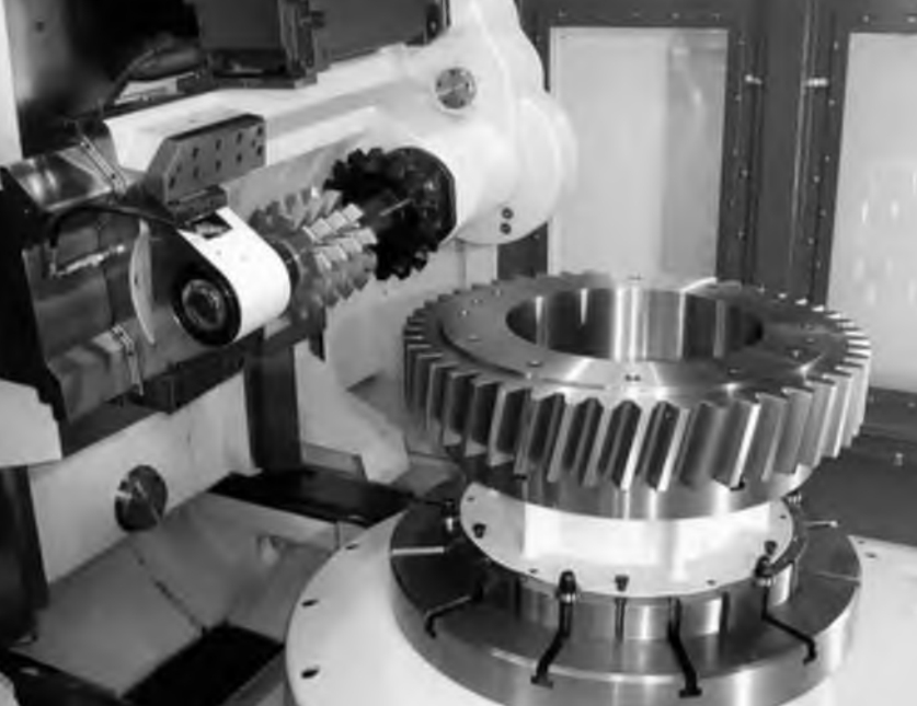
5.3 Rolling Test
A rolling test is conducted on a rolling tester between the grinding wheel and the pinion. The real contact mode during the rolling test is basically consistent with the contact form calculated by the TCA software, verifying the feasibility and correctness of the proposed method.
6. Conclusions
This research focuses on the active design and manufacturing of spiral bevel gear using a workpiece shaft – fixed method on a free – form surface machine tool. By taking meshing performance parameters as input variables, the micro – geometry of the pinion tooth surface is actively designed, and the machining parameters for the target tooth surface and depth are obtained. The method can ensure each contact path point on the pinion’s commonly used drive side, avoiding errors and manufacturing difficulties caused by poor workpiece axis motion accuracy. Experimental verifications demonstrate the effectiveness of the method. Future research could focus on optimizing contact attribute targets according to actual working conditions of gear pairs to further improve the performance of spiral bevel gear.