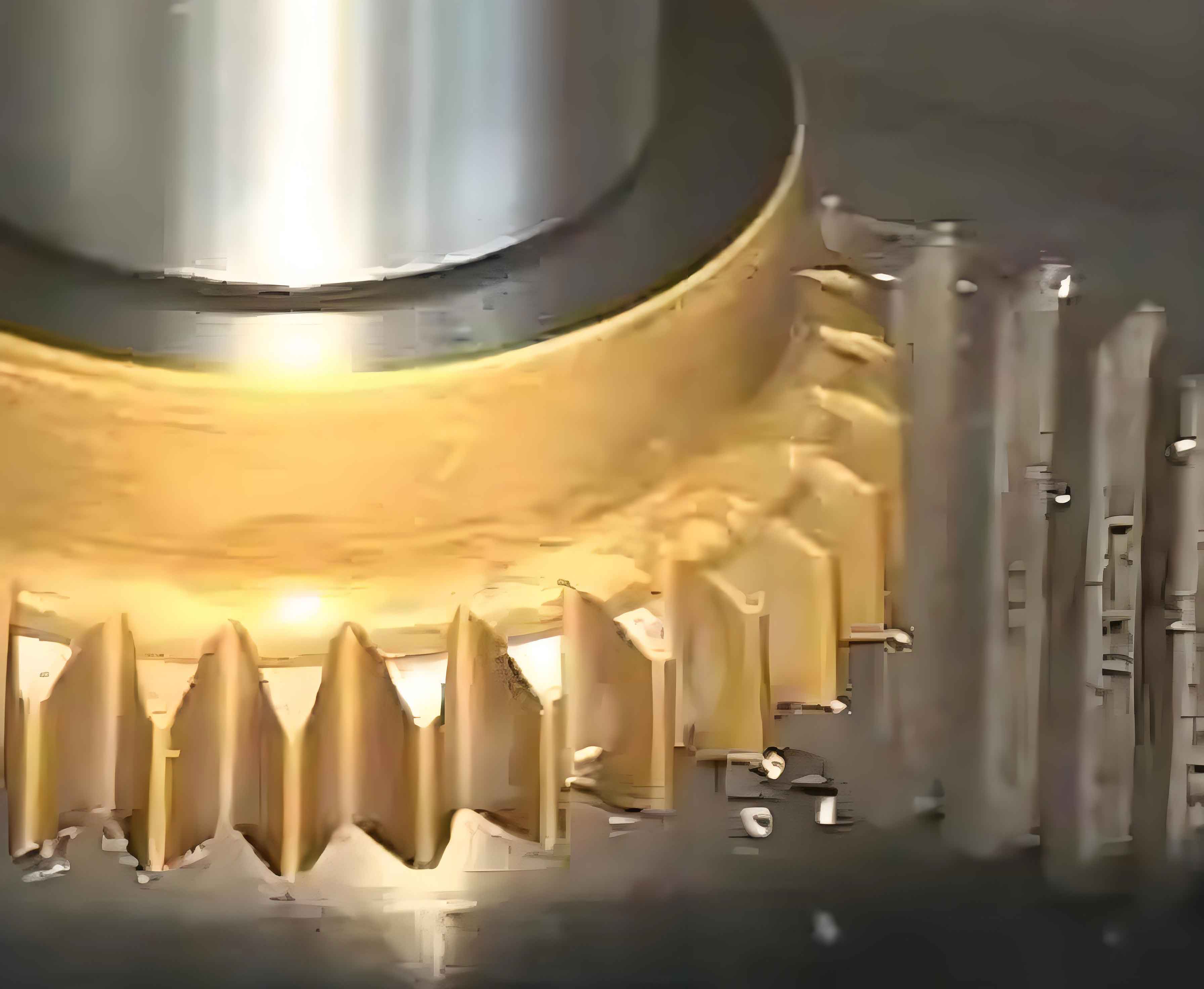
Precision in gear shaping directly depends on the accuracy of gear shaping cutters, making efficient grinding technology essential. This study addresses two core aspects: automatic tool setting during grinding wheel dressing using acoustic emission (AE) technology, and optimization of grinding wheel alignment during gear shaping cutter machining by integrating pitch deviation and tooth surface topology.

Automatic Tool Setting for Wheel Dressing
Traditional manual methods for detecting contact between diamond rollers and grinding wheels rely on visual/auditory cues, leading to inefficiencies and inaccuracies. AE technology overcomes this by capturing stress waves generated during initial contact. Key implementation steps include:
| Component | Specification | Function |
|---|---|---|
| AE Sensor | O3PZ1114014 (MARPOSS) | Captures AE signals from wheel-roller contact |
| Control Box | AE6000 | Processes signals with 0-10V threshold adjustment |
| Interface | D-SUB 15-pin | Connects to Siemens 828D PPU X242 I/O ports |
Signal processing follows:
$$ V_{\text{AE}} > V_{\text{limit}} \Rightarrow V_{\text{out}} = 0 \quad \text{(Contact)} $$
$$ V_{\text{AE}} < V_{\text{limit}} \Rightarrow V_{\text{out}} = 1 \quad \text{(No Contact)} $$
where \( V_{\text{limit}} \) is calibrated to minimize noise interference. Toolpath planning uses a point-retraction algorithm:
- Position roller at initial point \((X_{\text{DDD}}, Y_{\text{DDD}}, Z_{\text{DDD}} – \frac{\text{DIAMOND}}{2})\).
- Move along theoretical wheel profile coordinates \((X_J, Y_J)\).
- Trigger AE measurement:
MEASA[Y]=(1,1,-1) G01 Z=Z_J + \Delta Z. - On contact (\( \$AC\_MEA[1] = 1 \)), retract and update coordinates.
Siemens 828D Easy Screen interface enables parameter input, while G-code automates the sequence, reducing alignment time by 68% compared to manual methods.
Optimized Grinding Wheel Alignment
Blanks exhibit non-uniform grinding allowances due to pitch deviations (\(\delta_i\)) and topological deformations (\(\gamma\)). Traditional methods using pitch-averaged alignment cause tool wear and inaccuracies. The proposed optimization minimizes maximum grinding allowance (\(\mu_{ij}\)) by solving:
$$ \mu_{ij} = r_b \left( \left| \arctan\frac{X_{P_j}}{Y_{P_j}} \right| + \left| \arctan\frac{PB}{r_b} \right| – \sigma_{0z} – \frac{2\pi}{360} \Delta Z \right) – r_b \delta_i – r_b \tau_0 $$
where:
- \(r_b\): Base circle radius
- \(\sigma_{0z}\): Involute start angle at height \(\Delta Z\)
- \(\tau_0\): Wheel entry angle
Workflow for allowance calculation:
- Measure all pitch deviations using Renishaw LP2 probe at mid-tooth height.
- Capture 3×3 surface points per flank (Figure 2).
- Compute \(\mu_{ij}\) for \(\tau_0 \in [0.0002, 0.002]\) rad.
- Select \(\tau_0\) minimizing \(\max(\mu_{ij})\).
| Method | Min \(\max(\mu_{ij})\) (mm) | Optimal \(\tau_0\) (rad) |
|---|---|---|
| Pitch deviation only | 0.664 | 0.00081 |
| Topology only | 0.659 | 0.00083 |
| Integrated | 0.641 | 0.00088 |
MATLAB simulations confirm a 3.5–5.1% improvement in material removal efficiency.
CNC Implementation
Siemens 828D integrates:
- Easy Screen Interface: Inputs gear shaping parameters (module, teeth count, pressure angle).
- Probing System: Renishaw LP2 with MI 8-4 interface connected to X242 pins 4 (Input 1) and 8 (Ground).
- Measurement Cycles:
- Axis center calibration via 3-point measurement.
- Pitch deviation:
MEASA[A]=(1,2,-1) G01 A=3.5-SIGN/2 - Surface mapping: 9-point zigzag path at \(\frac{1}{4}\), \(\frac{1}{2}\), \(\frac{3}{4}\) tooth depth/width.
G-code calculates \(\tau_0\) and \(\mu_{\text{min}}\) using stored coordinates and Eq. (3). The optimized path reduces grinding passes by 22% for heat-treated gear shaping cutters.
Conclusion
AE-based dressing tool setting eliminates manual intervention, improving wheel profiling accuracy by ∼40%. Integrated alignment optimization reduces maximum grinding allowance by 4.2%, enhancing gear shaping efficiency and tool life. Future work will validate results on physical prototypes and extend the methodology to helical gear shaping cutters.
