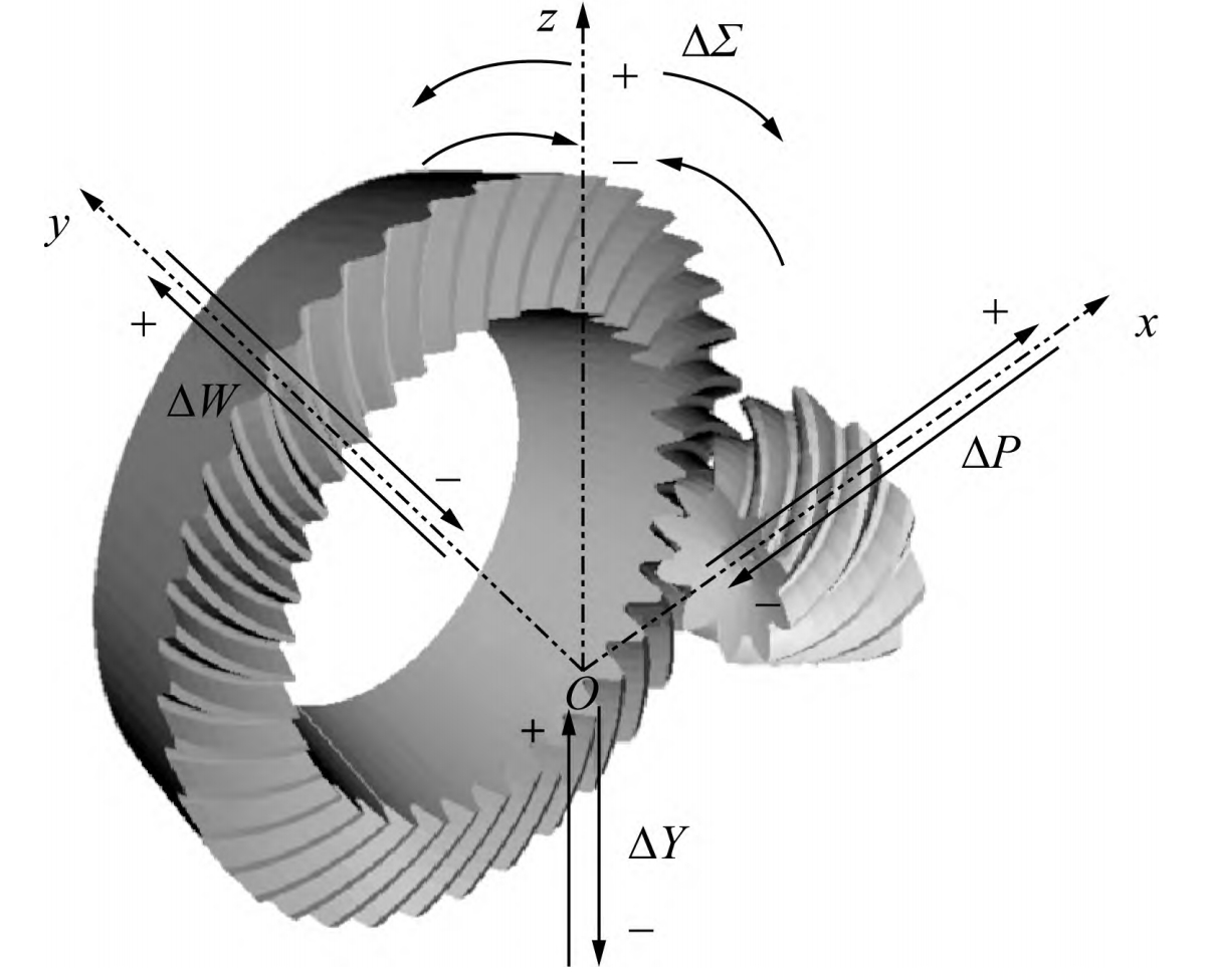
Abstract:
This paper focuses on the contact analysis of hypoid gears in automobile drive axles, proposing a tooth contact analysis method that combines analytical and finite element methods. By establishing a mathematical model based on the HFT method, tooth surface equations are derived. The transmission error is calculated using analytical methods, and the three-dimensional gear model is constructed based on numerical tooth surfaces. Finite element simulations are conducted in ABAQUS to obtain the three-dimensional contact area of the tooth surface. The results validate the correctness of the proposed method.

Keywords: hypoid gear; tooth contact analysis; tooth meshing model; finite element simulation; loaded tooth contact area
1. Introduction
Hypoid gears are widely used in various transmission devices due to their advantages of large contact ratio, smooth transmission, and high load capacity. In recent years, to evaluate the meshing performance of hypoid gears in automobile drive axles, researchers have conducted a series of studies on tooth contact analysis (TCA).
Table 1: Summary of Previous Research on TCA of Hypoid Gears
| Author | Method | Key Contributions |
|---|---|---|
| Wang et al. | HGT modeling and loaded contact analysis | Precise modeling and loaded tooth contact analysis of HGT hypoid gears |
| Du et al. | Klingelnberg hypoid gear modeling and contact analysis | Tooth surface modeling and contact analysis of Klingelnberg hypoid gears |
| Su et al. | Numerical tooth surface meshing simulation | Computerized meshing analysis of numerical tooth surfaces for spiral bevel gears |
2. Establishment of HFT Mathematical Model
The HFT (Helical Formed Tool) method is used to establish the mathematical model of hypoid gear machining. The tool and workpiece movement and position changes are considered to derive the tooth surface equation and unit normal vector.
3. Analytical Method for Solving Transmission Error
The TCA simulates the meshing process of the gear pair through mathematical methods. The transmission error is calculated based on the position and movement relationships during the meshing process.
The transmission error expression is derived as follows:
Δφ2=(φ2−φ(0)2)−z1z2(φ1−φ(0)1)Δφ2=(φ2−φ(0)2)−z1z2(φ1−φ(0)1)Δφ2=(φ2−φ(0)2)−z1z2(φ1−φ(0)1)
Table 2: Comparison of Transmission Error Calculated by Analytical Method and CAGE Software
| Method | Transmission Error Amplitude (μrad) |
|---|---|
| Analytical Method | 28 |
| CAGE Software | 28.5 |
4. Finite Element Simulation of Tooth Contact Area
The tooth surface equation is solved using the machining mathematical model, and the gear model is established in UG. The model is imported into ABAQUS for finite element simulation.
5. Experimental Validation
To further validate the finite element simulation results, grinding experiments and tooth surface error measurement experiments are conducted.
6. Conclusion
This paper studies the tooth contact analysis of hypoid gears using a combination of analytical and finite element methods. The transmission error curve is solved using analytical methods, and the three-dimensional contact area of the tooth surface is obtained through finite element simulation. The proposed method avoids complex curvature calculations in solving the contact ellipse and makes the display of the tooth contact area more realistic and intuitive. By comparing simulation results with MASTA software and tooth surface rolling inspection experiments, the correctness and feasibility of the proposed tooth contact analysis method are verified.
