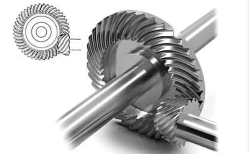
The cutting force modeling in spiral bevel gear machining using the forming method represents a critical foundation for machine tool design, vibration control, and process optimization. This study establishes an instantaneous cutting force prediction model through theoretical derivation and experimental validation, addressing the unique challenges in forming-based gear manufacturing.

1. Fundamental Principles of Forming Method
The forming process for spiral bevel gears maintains constant relative positioning between the cutter head and gear blank, with the tool feeding along its rotational axis. The key geometric relationship is expressed as:
$$r_{t2}(\mu, \theta) =
\begin{bmatrix}
(r_c \pm \mu \sin\alpha_m)\cos\theta \\
(r_c \pm \mu \sin\alpha_m)\sin\theta \\
-\mu \cos\alpha_m \\
1
\end{bmatrix}$$
Where \( r_c = r_0 \pm 0.5W \) represents the tool tip radius, with \( \alpha_m \) denoting the cutter profile angle. The machine coordinate system transformation matrix \( M_{mt} \) converts tool positions to the machining space.
2. Instantaneous Chip Geometry Analysis
The engagement angles for tool entry \( \theta_{st} \) and exit \( \theta_{ex} \) are calculated as:
$$
\theta_{st} \approx \beta_M – \arcsin\left(\frac{B}{2r_0 \cos\beta_M}\right) + 2k\pi
$$
$$
\theta_{ex} \approx \beta_M + \arcsin\left(\frac{B}{2r_0 \cos\beta_M}\right) + 2k\pi
$$
The instantaneous chip width \( b_{ew} \) and thickness \( h_{ew} \) for external blades are:
| Parameter | Expression |
|---|---|
| Chip Width | \( b_{ew}(t) = u_{ej}(\theta(t), z_j(t)) \) |
| Chip Thickness | \( h_{ew} = 2f_z \sin\alpha_e \) |
3. Material Constitutive Model
The Johnson-Cook material model calculates shear zone stress \( \tau \):
$$ \tau = \frac{1}{\sqrt{3}} \left(A + B\left(\frac{\xi}{\sqrt{3}}\right)^n\right) \left(1 + C \ln\frac{\dot{\xi}}{\dot{\xi_0}}\right)\left(1 – \left(\frac{T – T_r}{T_m – T_r}\right)^m\right) $$
Where strain \( \xi \) and strain rate \( \dot{\xi} \) distributions follow:
$$
\xi =
\begin{cases}
\frac{-\xi_m \cos\eta_e}{(q+1)V \cos\lambda_s \sin\phi_n (kh)^q} y^{q+1} & y \in [0, kh] \\
\frac{-\xi_m \cos\eta_e}{(q+1)V \cos\lambda_s \sin\phi_n (1-k)^q h^q} (h-y)^{q+1} + \frac{\cos\alpha_n \cos\eta_e}{\cos(\phi_n – \alpha_n)\cos\eta_s \sin\phi_n} & y \in [kh, h]
\end{cases}
$$
4. Cutting Force Prediction Model
The orthogonal cutting forces are decomposed into three axes:
| Force Component | Expression |
|---|---|
| Tangential | \( F_{Tqj} = \tau b_{qm}(t)h_{qm} + \tau b_{qv}h_{qv} \) |
| Radial | \( F_{Nqj} = \tau b_{qm}(t)h_{qm} + \tau b_{qv}h_{qv} \) |
| Axial | \( F_{Zqj} = \tau b_{qm}(t)h_{qm} + \tau b_{qv}h_{qv} \) |
The machine coordinate system forces are transformed using:
$$
\begin{cases}
F_{xt} = F_{Tqj} \sin\theta(t) – F_{Nqj} \cos\theta(t) \\
F_{yt} = F_{Tqj} \cos\theta(t) + F_{Nqj} \sin\theta(t) \\
F_{zt} = F_{Zqj}
\end{cases}
$$
5. Experimental Validation
Cutting tests were conducted on YKH2235 CNC gear milling machine with 42CrMo4 steel blanks. Key experimental parameters include:
| Parameter | Value |
|---|---|
| Spindle Speed | 120 rpm |
| Feed Rate | 20 mm/min |
| Cutter Diameter | 127 mm |
| Blade Profile Angle | 14° (external), 24° (internal) |
The model demonstrates prediction errors below 14% across all force components:
| Force Direction | Average Error |
|---|---|
| X-axis | 9.24% |
| Y-axis | 13.18% |
| Z-axis | 13.25% |
6. Process Optimization Implications
The established model enables:
- Cutting parameter optimization for spiral bevel gear manufacturing
- Vibration suppression through force prediction
- Tool wear monitoring based on force signatures
- Machine tool structural design verification
This research provides a theoretical foundation for improving the efficiency and precision in spiral bevel gear production using forming methods. Future work will focus on thermal-mechanical coupling effects and multi-blade interaction modeling.
