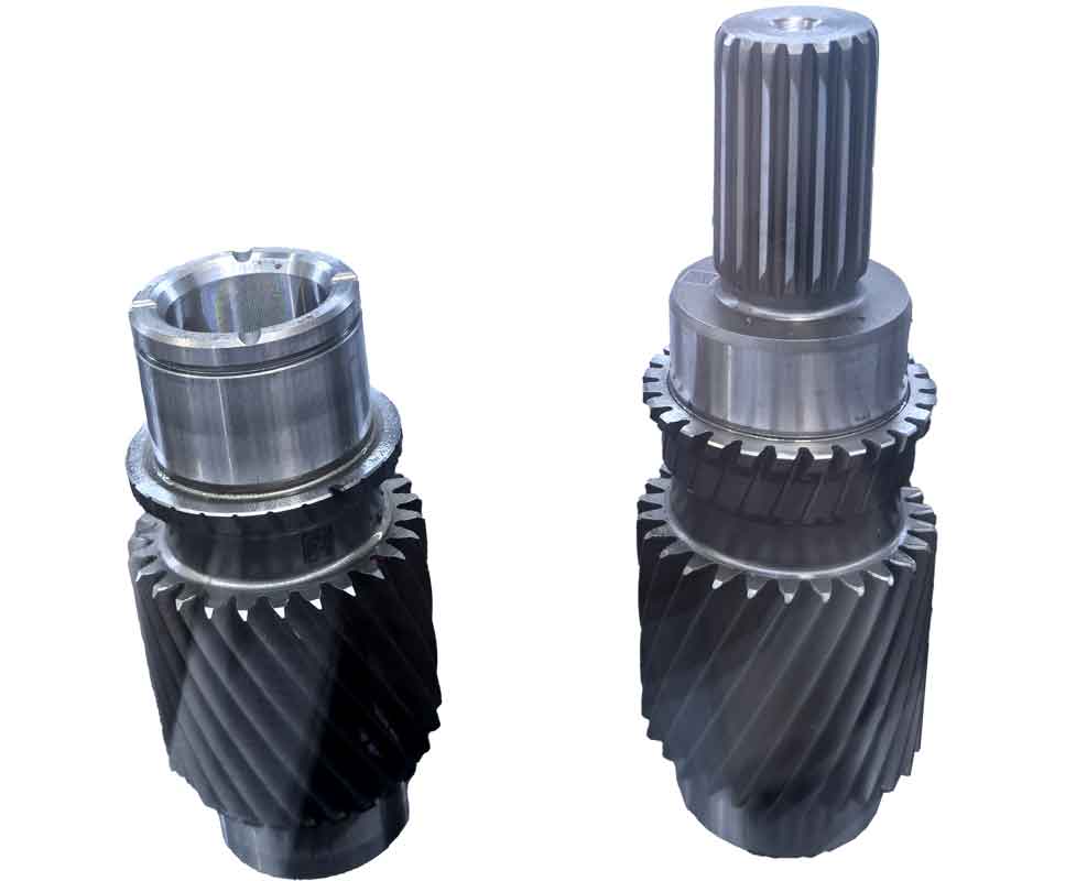
Spiral bevel gears are critical components for transmitting motion and power between intersecting or skew axes. Their complex tooth geometry demands high-precision manufacturing, where gear cutting efficiency and surface quality significantly impact performance. This research addresses key challenges in CNC gear cutting: dynamic cutting force prediction, parameter optimization, and surface residual height control. We establish physics-based models validated experimentally, enabling intelligent machining process design.
1. Cutting Force Modeling for Form Milling of Gear Blanks
Form milling generates gear teeth through synchronized cutter rotation and workpiece feed without generating motion. The instantaneous undeformed chip geometry governs cutting forces. For a cutter with radius \(r_c\) and pressure angle \(\alpha\), the chip thickness \(h\) and width \(b\) for outer (\(e\)) and inner (\(i\)) blades are:
$$h_{ew} = 2f_c \sin \alpha_e + \Delta h_{w,j}, \quad b_{ew} = u_{ej} – u_{e0}$$
$$h_{iw} = 2f_c \sin \alpha_i + \Delta h_{w,j}, \quad b_{iw} = u_{ij} – u_{i0}$$
where \(f_c\) is feed per tooth, \(\Delta h\) accounts for blade runout, and \(u\) is cutter engagement depth. The tangential cutting force \(F_T\) combines blade edge and flank contributions:
$$F_{Tmj} = C_s(b_{mw} h_{mw} + b_{mt} h_{mt})$$
with \(C_s\) as specific cutting force calibrated via orthogonal experiments. Radial \(F_R\) and axial \(F_A\) forces follow:
$$F_{Rmj} = f_{TR} F_{Tmj}, \quad F_{Amj} = f_{TA} F_{Tmj}$$
| Parameter | Value | Parameter | Value |
|---|---|---|---|
| Workpiece Material | 20CrNiMo | Blade Material | Coated HSS |
| \(C_s\) (N/mm²) | 1.856 | Exponent \(q\) | 0.25 |
| \(f_{TR}\) (outer blade) | 0.346 | \(f_{TA}\) (outer blade) | 0.135 |
| \(f_{TR}\) (inner blade) | 0.362 | \(f_{TA}\) (inner blade) | -0.126 |
Experimental validation showed ≤15% deviation between predicted and measured forces across varying feeds (20–40 mm/min) and speeds (29–45 rpm).
2. Cutting Force Modeling for Generating Method in Pinion Roughing
Generating gear cutting simulates gear meshing via CNC axis interpolation. Undeformed chip area \(A\) is derived from intersecting cutter and workpiece surfaces. For outer blades:
$$A_{oi} = \frac{1}{2} s_i^2 \sin(\angle N_i M_i Q_i)$$
where \(s_i\) is contact depth, and \(\angle N_i M_i Q_i\) is the angle between consecutive blade paths. Tangential force \(F_T\) relates to chip area:
$$F_T(t) = C_s A_k(t), \quad k \in \{o,i\}$$
Power consumption \(P_c\) and motor input \(P_m\) are:
$$P_c(t) = F_T(t) v_c, \quad P_m(t) = \frac{\sqrt{3} U I \cos \phi}{\eta_m}$$
where \(v_c\) is cutting speed, \(U\) and \(I\) are voltage/current, \(\cos \phi\) is power factor, and \(\eta_m\) is motor efficiency. Validation via spindle power monitoring confirmed model accuracy under varied \(v_c\) (32–43 m/min) and interpolated feed \(v_{xy}\) (20–30 mm/min).

3. Variable Feed Rate Control Under Near-Constant Cutting Force
Traditional constant-feed gear cutting causes force fluctuations up to 100% during form milling. We implement variable feed \(f_{\text{lim}}\) using linearized force-feed relationship:
$$f_{\text{lim},i} = \frac{(F_{\text{lim}} – F_{1,i}) (f_2 – f_1)}{F_{2,i} – F_{1,i}} + f_1$$
where \(F_{1,i}\), \(F_{2,i}\) are forces at feeds \(f_1\), \(f_2\), and \(F_{\text{lim}}\) is the desired force. Tests with \(F_{\text{lim}}\) = 2,200 N reduced force variation by 60% and cycle time by 23.8% compared to constant 40 mm/min feed.
4. Cutting Parameter Optimization Using Harmony Search
Harmony Search Algorithm (HSA) optimizes gear cutting parameters for productivity and cost. For form milling, minimize time \(T_t\):
$$T_t = \frac{L_r}{f} + \frac{L_b}{v_{\text{max}}} + \frac{2\pi z_d}{z_2 \omega_g} + T_p$$
subject to:
$$\begin{cases}
v_{\text{min}} \leq \frac{\pi n r_c}{30} \leq v_{\text{max}} \\
P_m \geq \max(F_T v_c)/\eta \\
T = \frac{C_v k_V r_c^m}{v_c^m a_c^{x_v} f^{y_v} B^{t_v} z^{p_v}} \geq [T]
\end{cases}$$
For generating gear cutting, multi-objective optimization minimizes time \(T_m\) and cost \(C\):
$$\min \left( \lambda_1 \frac{T_m – T_{\min}}{T_{\max} – T_{\min}} + \lambda_2 \frac{C – C_{\min}}{C_{\max} – C_{\min}} \right)$$
HSA parameters: \(N=3\), HMS=10, HMCR=0.95, PAR=0.45. Results show 16.7% time reduction versus empirical settings.
| Objective | \(v_c\) (m/min) | \(v_{xy}\) (mm/min) | \(\Delta\theta\) (°) | Time (min) |
|---|---|---|---|---|
| High Efficiency | 47.62 | 75.52 | 0.104 | 25.79 |
| Low Cost | 37.64 | 69.62 | 0.173 | 27.57 |
| Balanced | 43.27 | 73.50 | 0.126 | 25.89 |
| Empirical | 30–45 | – | – | 30.75 |
5. Surface Residual Height in Finish Gear Cutting
Residual height \(\delta\) in generating gear cutting arises from discrete blade paths. For contact point \(M_i\) between blades \(i\) and \(i+1\):
$$\mathbf{r}_{pi}(\theta_x, \phi_x) + \delta_i \mathbf{n}_{pi}(\theta_x, \phi_x) = \mathbf{r}_{pi}(M_i)$$
Mean residual height \(\bar{\delta}\) and surface roughness \(R_s\) are:
$$\bar{\delta} = \frac{1}{N} \sum_{i=1}^N \delta_i, \quad R_s = \frac{1}{2N} \sum_{i=1}^N \delta_i$$
Parameter influence on \(\bar{\delta}\) (convex side):
| \(\Delta\theta\) (°) | \(\bar{\delta}\) (µm) | \(R_s\) (µm) | Measured \(R_a\) (µm) |
|---|---|---|---|
| 1.0 | 2.204 | 1.102 | – |
| 0.5 | 0.553 | 0.276 | 1.6 |
| 0.25 | 0.138 | 0.069 | 0.32 |
Reducing interpolation angle \(\Delta\theta\) from 1° to 0.25° decreases \(\bar{\delta}\) by 16×. Cutting speed \(v_c\) (25–50 m/min) and feed \(v_{xy}\) (20–60 mm/min) cause < 15% \(\bar{\delta}\) variation.
6. Conclusions
Physics-based models for dynamic cutting forces in spiral bevel gear cutting enable accurate prediction and control. Variable feed rate optimization reduces force fluctuations by 60% and cycle times by 23.8%. HSA-based parameter optimization achieves 16.7% higher productivity versus empirical methods. Residual height modeling confirms interpolation angle \(\Delta\theta\) dominates surface quality, with \(R_s \propto (\Delta\theta)^2\). These advances support intelligent CNC gear cutting systems for high-efficiency, precision manufacturing.
