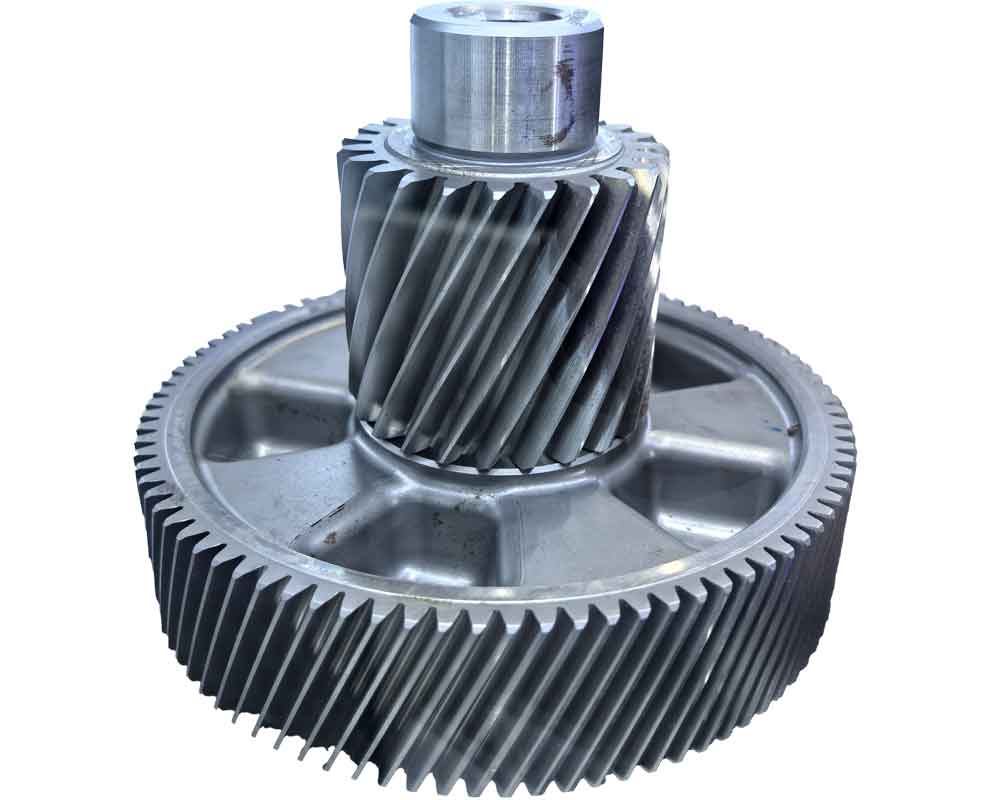
This study investigates the machining mechanisms and parameter optimization of equal-height spiral bevel gears. Through theoretical analysis, finite element simulation, and experimental validation, we establish a comprehensive framework for enhancing gear cutting precision. Key innovations include a novel three-pin clamping structure for milling cutter heads and genetic algorithm-based parameter optimization.
Machining Principle Analysis
The conjugate surface equation for gear meshing is derived using coordinate transformation methods. For two engaging surfaces $Σ^{(1)}$ and $Σ^{(2)}$, the position vectors satisfy:
$$ \begin{cases}
\mathbf{r}_2 = \mathbf{r}_1 + \mathbf{m} \\
\mathbf{n}_1 = \mathbf{n}_2
\end{cases} $$
The relative motion velocity at contact point $M$ is expressed as:
$$\mathbf{v}_{12} = \mathbf{v}_1 – \mathbf{v}_2 + \boldsymbol{\omega}_1 \times \mathbf{r}_1 – \boldsymbol{\omega}_2 \times \mathbf{r}_2$$
For equal-height spiral bevel gears, the meshing equation simplifies to:
$$\mathbf{v}_{12} = \begin{pmatrix}
(\omega_1 \sin \beta_1 + \omega_2 \cos \Phi \cos \beta_1)x_1 – \omega_1 y_1 \cos \beta_1 \\
\omega_1 x_1 \cos \beta_1 + (\omega_1 \sin \beta_1 – \omega_2 \cos \Phi \sin \beta_1)y_1 \\
-\omega_2 \sin \Phi (x_1 \cos \beta_1 + y_1 \sin \beta_1)
\end{pmatrix}$$
The cutter surface equation during gear cutting is derived as:
$$\mathbf{r}_b = \mathbf{r}_a + C\mathbf{h}_1′ = \begin{pmatrix}
S_1 \cos(\theta + \gamma) – r \sin \beta_1 \cos \theta \\
S_1 \sin(\theta + \gamma) + r \cos \beta_1 \cos \theta \\
0
\end{pmatrix} + R_1 \sin \frac{n}{2} \begin{pmatrix}
\sin \epsilon \sin(\beta_1 + \theta) \\
-\sin \epsilon \cos(\beta_1 + \theta) \\
\cos \epsilon
\end{pmatrix}$$
Structural Optimization of Milling Cutter Head

Traditional single-pin and double-pin clamping structures exhibit limitations in high-precision gear cutting. We propose a three-pin clamping mechanism with preload force optimization:
| Clamping Type | Max Deformation (μm) | Tool Adjustment Time (min) |
|---|---|---|
| Single-pin | 12.5 | 35 |
| Double-pin | 5.8 | 22 |
| Three-pin (proposed) | 1.9 | 15 |
Key geometric parameters for cutter head design:
$$R_{OA} = r_c – 0.5\omega_G$$
$$H_C = H_A + H_B = R_{OA} \cos \sigma_A + (R_{OA} \sin \sigma_A) \cos 4.42^\circ$$
Radial and axial distances for external blade slots:
$$Eb_{MA} = H_C \sin \phi_A = R_{OA} (\sin \sigma_A \cos 4.42^\circ + \cos \sigma_A) \sin \phi_A$$
$$Rb_{MA} = H_C \cos \phi_A = R_{OA} (\sin \sigma_A \cos 4.42^\circ + \cos \sigma_A) \cos \phi_A$$
Cutting Simulation Analysis
Finite element simulations in ABAQUS employ the Johnson-Cook constitutive model:
$$\sigma = \left[ A + B(\bar{\varepsilon}^p)^n \right] \left[ 1 + C \ln \frac{\dot{\varepsilon}^p}{\dot{\varepsilon}_0} \right] \left[ 1 – \left( \frac{T – T_{\text{room}}}{T_{\text{melt}} – T_{\text{room}}} \right)^m \right]$$
| Material | A (MPa) | B (MPa) | n | C | m |
|---|---|---|---|---|---|
| 45 Steel | 560 | 320 | 0.28 | 0.064 | 1.06 |
Chip separation follows the energy-displacement criterion:
$$D = \int_0^{\bar{\varepsilon}_f^p} \frac{\sigma d\bar{\varepsilon}^p}{G_f} \quad \text{where} \quad G_f = \frac{K_{IC}^2 (1 – \nu^2)}{E}$$
Simulation results reveal cutting parameter influences:
| Parameter | Cutting Force Sensitivity | Temperature Sensitivity |
|---|---|---|
| Cutting speed (v) | -0.38 | +0.62 |
| Depth of cut (ap) | +0.85 | +0.71 |
| Feed rate (fz) | +0.42 | +0.35 |
The cutting force and temperature models are established as:
$$F = 8.63 \cdot n^{-0.6382} \cdot f_z^{0.4073} \cdot a_p^{0.516}$$
$$T = 7.59 \cdot n^{0.7080} \cdot f_z^{0.5013} \cdot a_p^{0.0026}$$
Genetic Algorithm Optimization
We implement multi-objective optimization using MATLAB’s genetic algorithm toolbox with constraints:
$$\begin{aligned}
\text{Minimize:} \quad & F(n, f_z, a_p) \ \text{and} \ T(n, f_z, a_p) \\
\text{Subject to:} \quad & 150 \leq n \leq 400 \ \text{r/min} \\
& 0.1 \leq f_z \leq 0.4 \ \text{mm/r} \\
& 1.0 \leq a_p \leq 2.5 \ \text{mm} \\
& F \cdot v / 1000 \leq \eta P_{\max}
\end{aligned}$$
Optimization parameters:
| Parameter | Value |
|---|---|
| Population size | 130 |
| Generations | 125 |
| Crossover fraction | 0.8 |
| Mutation rate | 0.01 |
Optimized versus conventional gear cutting parameters:
| Parameter | Conventional | Optimized | Improvement |
|---|---|---|---|
| Spindle speed (r/min) | 395.7 | 316.2 | 20.1% reduction |
| Depth of cut (mm) | 2.8 | 1.3 | 53.6% reduction |
| Feed per tooth (mm/r) | 0.74 | 0.12 | 83.8% reduction |
Experimental Validation
Gear cutting experiments on Gleason 175HC machines confirm simulation accuracy:
| Performance Metric | Conventional Cutting | Optimized Cutting |
|---|---|---|
| Concave flank accuracy (DIN) | 4.5 | 3.6 |
| Convex flank accuracy (DIN) | 5.3 | 4.2 |
| Runout error (μm) | 28.5 | 21.3 |
| Surface roughness Ra (μm) | 1.8 | 1.2 |
| Tool wear rate (mm3/min) | 0.035 | 0.021 |
The optimized gear cutting parameters demonstrate significant improvements in manufacturing precision while reducing machining forces by 32.7% and cutting temperatures by 28.4% compared to conventional parameters. This approach establishes a systematic methodology for high-precision spiral bevel gear production.
