
Laser cutting equipment mainly uses heat energy generated by laser beam emitted by laser to cut pipes with motion mechanical system. The cut pipes are controlled by intelligent system and can achieve high quality and high efficiency production purpose.Cutting precision of laser cutting equipment is the first factor to judge the quality of equipment, and the important component affecting cutting accuracy is chuck. The rotating precision of chuck for clamping parts and the repetitive positioning accuracy determine the machining accuracy of the whole laser cutting equipment. The rotating precision of chuck is mainly determined by the gear pair of driving chuck, so the design of driving gear pair of chuckManufacturing quality directly affects the processing accuracy of laser cutting equipment.
1. Selection of gear pair materials
Cup drive gear auxiliary drive gear and driven gear can be selected: common steel, 45 steel, etc., medium carbon alloy steel, 40Cr, 42CrMo, low carbon alloy steel, 20CrMnMo, 17Cr2Ni2Mo, etc.
Different materials have different heat treatment methods and mechanical properties, which determine the strength of gear pairs. Generally 45 steel < 40Cr (42CrMo) < 20CrMnMo (17Cr2Ni2Mo).
2. Selection of heat treatment method for gear pair
The chuck drive gear secondary drive gear and driven gear have different heat treatment methods depending on the material.
Normal steel 45 generally chooses quenching treatment, hardness (240-260) HBS, induction hardening of teeth, hardness (45-50) HRC.
Medium carbon alloy steel 40Cr or 42CrMo generally chooses quenching treatment, hardness (240-280) HBS, induction hardening of teeth, hardness (50-55) HRC.
Low carbon alloy steel 20CrMnMo or 17Cr2Ni2Mo generally chooses normalizing + high temperature tempering pretreatment, tooth carburizing, whole quenching + low temperature tempering, tooth hardness (58-62) HRC, core hardness (30-42) HRC.
3. Selection of Gear Pair Dimensions
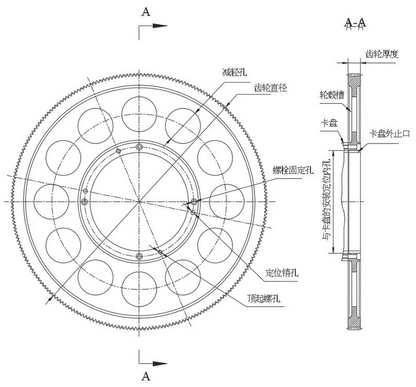
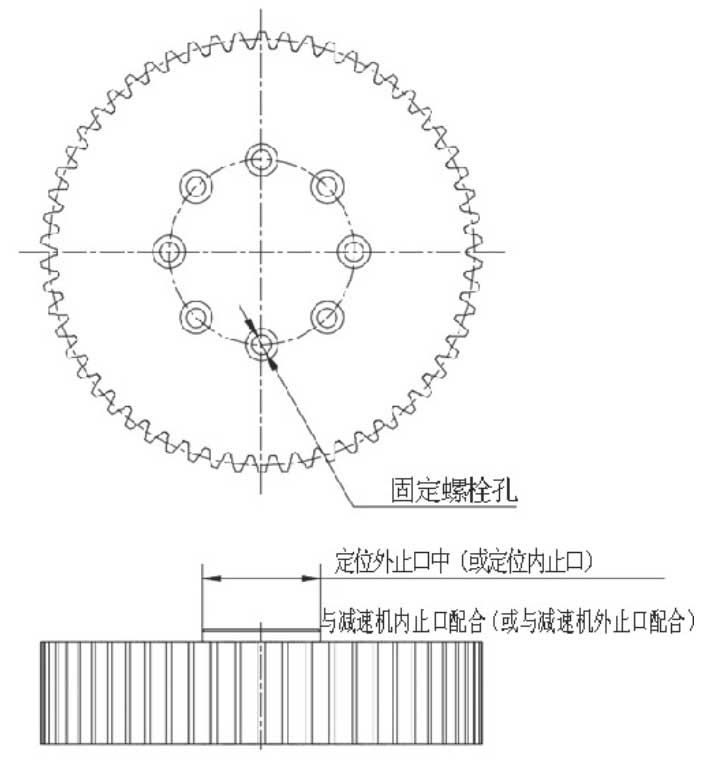
In order to reduce the moment of inertia of chuck, select low-power motor and reduce power consumption, the size and weight of driven gear in gear pair should be reduced as much as possible as shown in the figure; the thickness of gear can generally be controlled in 20-40Mm can be used to reduce the weight of the gear by increasing the number of reducing holes and the diameter and depth of reducing holes as much as possible and reducing the diameter of the gear wheels within a reasonable range of use so as to minimize the moment of inertia as possible.
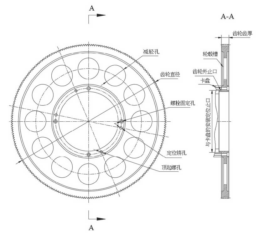
There are two connection modes between driven gear and chuck, one is shown in Figure . The inner gear bore is fitted with the outer chuck stop; the general inner gear bore is fitted with the outer chuck stop, e.g. G6/h5; the other is fitted with the outer gear stop and the inner chuck hole, and the general outer gear stop is fitted with the inner chuck hole, e.g. H6/g5; the two connectors are fitted.Type A is fixed by bolts, which can be fixed by 4 or 6 or 8 bolts, and matched with pin holes and positioning pins in case of qualified pitch and circle runout. For easy disassembly, gear machines jacking screw holes.
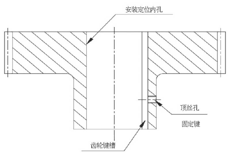
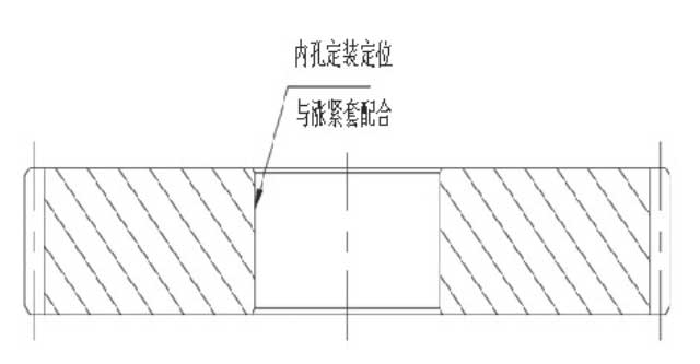
Drive gears should also be sized to minimize moment of inertia in the same way as driven gears.The installation mode of the drive gear needs to be determined according to the installation interface of the reducer of the customer. Generally, there are three ways to install the drive gear, one is through key connection as shown in the figure, the inner hole is positioned with the shaft of the reducer and the top wire hole is fixed; the other is through flange connection as shown in the figure, the gear has positioning outer stop or positioning inner stop, which is fitted with the internal stop of the reducer or the external stop of the reducer and is fixed through fixing.Fixed bolt holes; one is connected by a tensioning sleeve as shown in Fig. 5. The inner holes are positioned in conjunction with the tensioning sleeve and then fixed with the reducer shaft.
4. Selection of Gear Pair Module, Tooth Number and Accuracy
The total moment of inertia of the chuck and the machined parts of the laser cutting equipment is not too large, and the power of the driving motor is less than 10 kW. Generally, 1.8 kW, 2.9 kW, 4 kW, 5 kW and so on are selected according to the size of the chuck.According to GB/T 3480-2008 Calculation of Bearing Capacity of Spur and Helical Gears, 1.5, 2 or 3 can be selected as the modulus; the number of teeth can be determined according to the transmission speed ratio of the driving gear and driven gear.
To ensure smoothness and low noise of transmission as well as reasonable manufacturing cost and good workmanship, the tooth accuracy of general gear pairs is selected as 6-level accuracy (precision of involute cylindrical gear GB/T 10095-2008).
5. Selection of Gear Pair Manufacturing Process
For material selection of common steel 45, etc. or medium carbon alloy steel 40Cr, 42CrMo, the manufacturing processes are: blanking – rough turning – quenching treatment – finishing turning – scratching – gear hobbing (insertion) processing – induction hardening – finishing turning – scratching drilling (keyway processing) – grinding – gear grinding – final inspection. Among them, the precision turning and gear hobbing (insertion) procedures before induction hardening are particularly important, and its direct shadowProcessing costs and quality of later processes are loud.
Select low carbon alloy steel 20CrMnMo for material.17Cr2Ni2Mo and other manufacturing processes are: blanking – rough turning – normalizing + high temperature tempering pretreatment – semi-finishing turning – scratching – gear hobbing (insertion) processing – carburizing quenching – finishing turning – scratching drilling (keyway processing) – grinding – teeth grinding – final inspection. Among them, the retention of semi-finishing turning and gear hobbing (insertion) processes before carburizing quenching is particularly important, which directly affects the processing cost of the rear process.Quality.
In recent years, with the rapid development of laser cutting industry, the precision requirement of laser cutting equipment becomes higher and higher, so the precision requirement of each component becomes higher and higher.As its main component, the accuracy of chuck determines the precision of laser cutting equipment. Through the above introduction, the design and manufacture of chuck driving gear pair used in laser cutting equipment are introduced. More particularly, the design and manufacture of driving gear pair connected with reducer and driven gear connected with chuck are involved.
The design and manufacture of chuck drive gear pair used in laser cutting equipment in this paper covers almost all the methods of design and manufacture of chuck drive gear pair, which provides basis for the design and manufacture of gear pair.