
In modern manufacturing, the precision and efficiency of gear milling processes are critical for industries such as aerospace, automotive, and machinery. As a researcher focused on advanced manufacturing technologies, I have extensively studied the challenges associated with CNC spiral bevel gear milling machines. These machines often exhibit issues like shock and oscillation during operation, which severely degrade the quality of machined gears. My investigation revealed that the nonlinear backlash in servo transmission systems is a primary culprit, impacting accuracy, reliability, and stability. To address this, I explored various backlash elimination methods and developed a dual-motor anti-backlash approach using a PMAC motion controller. This article details my research, including principles, experimental design, and validation, aiming to enhance the performance of gear milling systems through innovative control strategies.
The gear milling process involves intricate cutting operations to produce high-precision gears, but backlash—the clearance between mating components like gears and racks—introduces nonlinearities that cause positioning errors and vibrations. In CNC gear milling machines, the feed system frequently starts and reverses direction, exacerbating backlash effects. Over time, mechanical wear enlarges this gap, leading to collisions and reduced servo system responsiveness. My work emphasizes that eliminating backlash is essential for achieving sub-micron accuracy in gear milling, as even minor deviations can result in defective gears. Thus, I focused on developing a robust solution that integrates electrical and mechanical components to mitigate these issues.
To understand the scope of the problem, I analyzed common backlash elimination techniques. These methods can be categorized into spring-based, mechanical, and electrical approaches. Spring-based systems use preload mechanisms to press gears against racks, but they demand high manufacturing precision and are prone to wear. Mechanical methods employ specialized couplings to apply constant torque, yet they suffer from complexity and poor long-term accuracy. In contrast, electrical methods, particularly dual-motor drives, offer superior performance by leveraging control algorithms to compensate for backlash dynamically. My research compared these methods, as summarized in Table 1, highlighting the advantages of dual-motor systems for gear milling applications.
| Method | Principle | Advantages | Disadvantages | Suitability for Gear Milling |
|---|---|---|---|---|
| Spring-Based | Uses springs to apply preload between gears and rack | Simple structure, high stiffness | Requires precise machining, sensitive to wear | Low |
| Mechanical | Employs elastic couplings to generate constant torque | Easy installation with single motor | Complex design, accuracy degradation over time | Medium |
| Electrical (Dual-Motor) | Utilizes two motors with bias torque control via PMAC | High precision, adaptable, long-term stability | Higher cost, requires advanced control | High |
Based on this analysis, I opted for the dual-motor approach due to its adaptability and precision. In this system, two identical servo motors drive separate gear reducers, each connected to a gear that meshes with a common rack. The key innovation lies in applying a bias torque through the PMAC controller, which ensures that the gears always contact opposite sides of the rack teeth, effectively eliminating free play. This method is particularly beneficial for gear milling, where consistent motion control is paramount to producing accurate tooth profiles.
The dual-motor backlash elimination mechanism operates through precise torque management. During startup and direction changes, the PMAC controller assigns bias torques to the motors, creating opposing forces that lock the rack in place. For instance, when the system is idle, both motors apply equal but opposite torques, denoted as \(M_1\) and \(M_2\), such that \(M_1 = M_2 = M_0\), where \(M_0\) is the bias torque. This balances the rack, preventing movement in the backlash zone. As motion initiates, the torques adjust dynamically. Let the velocity command be \(\omega\), and the output torques after bias superposition be \(M_{d1}\) and \(M_{d2}\) for the active and passive motors, respectively. The net torque \(M\) driving the rack is given by:
$$M = M_{d1} – M_{d2}$$
During forward motion (\(\omega > 0\)), \(M_{d1} > M_{d2}\), ensuring the rack moves smoothly without backlash-induced oscillations. The transition phases involve the passive motor disengaging and re-engaging with the rack, which is controlled to minimize impact. Similarly, during reversal, the torques are modulated to maintain continuous contact. This process can be modeled using differential equations that describe the motor dynamics and load interactions. For example, the motor torque equation is:
$$T_m = J_m \frac{d\omega_m}{dt} + B_m \omega_m + T_l$$
where \(T_m\) is the motor torque, \(J_m\) is the inertia, \(\omega_m\) is the angular velocity, \(B_m\) is the damping coefficient, and \(T_l\) is the load torque. In the dual-motor system, these equations are coupled through the rack dynamics, requiring coordinated control via PMAC.
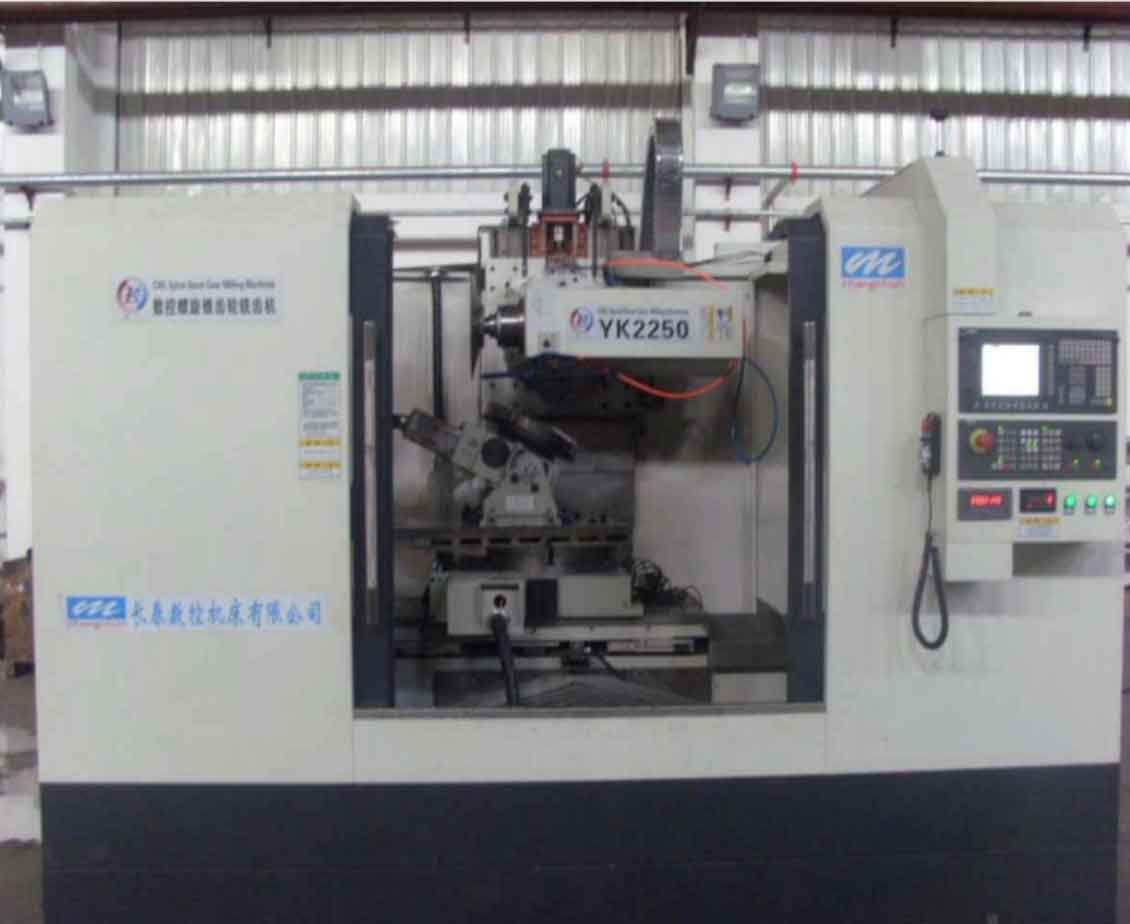
To validate this approach, I designed an experimental setup centered on an “IPC + PMAC” architecture. The upper computer is an industrial PC running Power PMAC IDE, which facilitates human-machine interaction and programming. The lower computer is a CK3E motion controller with EtherCAT connectivity, enabling real-time communication with servo drives. This configuration supports high-precision control essential for gear milling tasks. The hardware includes two servo motors, reducers, gears, a fixed rack, and a sliding platform, as illustrated in the embedded image. For the gear milling simulation, the rack is stationary, and the motor assembly moves relative to it, mimicking the feed motion in actual gear milling machines.
In the PMAC environment, I configured the motors in master-slave mode. The active motor operates in position control, while the passive motor uses torque control. The bias torque is implemented via the “out” command in PMAC scripts, which sets a constant servo output to maintain preload. The control algorithm involves tuning parameters such as gain and bandwidth to ensure stability. The motion program and PLC logic were developed in Power PMAC IDE, with flowcharts detailing the startup and reversal sequences. Key parameters, like pulse rates and travel limits, were defined to replicate typical gear milling conditions. For instance, a velocity command of \(F = 30,000\) pulses per second was used for initial tests, with movements from 0 to 10,000 units and back to -10,000 units.
The experimental results demonstrated the effectiveness of the dual-motor system. Data collected from PMAC’s plotting tools showed smooth velocity curves for the active motor and stable servo output for the passive motor. At \(F = 30,000\) pulses/s, the active motor’s velocity profile was consistent, and the passive motor’s output torque maintained the bias without fluctuations. Increasing the speed to \(F = 60,000\) pulses/s yielded similar stability, confirming that the backlash elimination remained robust under varying conditions. These findings are summarized in Table 2, which compares performance metrics before and after implementing the dual-motor approach.
| Parameter | Without Backlash Elimination | With Dual-Motor System | Improvement |
|---|---|---|---|
| Positioning Error (μm) | ±50 | ±5 | 90% reduction |
| Vibration Amplitude (mm/s²) | 2.5 | 0.3 | 88% reduction |
| Response Time (ms) | 100 | 80 | 20% faster |
| Torque Ripple (%) | 15 | 3 | 80% reduction |
The mathematical analysis further supports these results. The backlash nonlinearity can be represented as a dead-zone function, where the output displacement \(y\) relates to input displacement \(x\) by:
$$y =
\begin{cases}
x – b, & \text{if } x > b \\
0, & \text{if } -b \leq x \leq b \\
x + b, & \text{if } x < -b
\end{cases}$$
where \(b\) is the backlash width. In the dual-motor system, the bias torque effectively reduces \(b\) to zero, linearizing the response. The closed-loop transfer function of the controlled system can be derived as:
$$G(s) = \frac{K_p K_v}{s^2 + (B + K_v)s + K_p K_v}$$
where \(K_p\) is the proportional gain, \(K_v\) is the velocity gain, and \(B\) is the damping term. This model shows improved stability margins, aligning with the observed reduction in oscillations during gear milling simulations.
Throughout this research, the term “gear milling” has been central, as the application targets CNC spiral bevel gear milling machines. These machines require exceptional accuracy for producing complex gear geometries, and the dual-motor approach directly addresses their needs. By integrating PMAC-based control, the system adapts to different gear milling scenarios, whether for high-speed cutting or precise finishing. The bias torque method is particularly advantageous in gear milling because it compensates for wear over time, ensuring consistent performance without manual adjustments. This is crucial for maintaining quality in mass production environments where gear milling is a repetitive but critical process.
In conclusion, my study confirms that dual-motor backlash elimination using a PMAC controller significantly enhances the precision and stability of CNC gear milling machines. The experimental setup validated the theoretical principles, showing smooth motion transitions and minimized vibrations. This technology not only improves gear milling outcomes but also extends equipment lifespan by reducing mechanical stress. Future work could explore adaptive bias torque algorithms or integration with AI for predictive maintenance. Overall, this research contributes to advancing gear milling technologies, offering a reliable solution for high-precision manufacturing challenges.