
The development and refinement of ultrasonic vibration systems for gear honing applications represent a significant advancement in precision manufacturing. A core challenge in implementing such systems lies in the dynamic nature of the gear honing process itself, where the machining load can vary substantially. To maintain stable and efficient material removal, the ultrasonic vibration system must possess the capability for automatic frequency and energy tuning. This necessitates a reliable and accurate feedback mechanism to monitor the system’s resonant state and vibrational energy in real-time. Traditional methods for measuring ultrasonic energy, such as mechanical probes for sound intensity or radiation pressure techniques, often suffer from drawbacks like field disturbance or limited effective range. Laser-based displacement measurements, while non-invasive, may lack the necessary frequency response to accurately track the high-frequency oscillations of an ultrasonic tool. Therefore, developing a practical, precise, and convenient testing methodology is paramount for the successful implementation of automatic tuning in gear honing systems. This study focuses on establishing such a methodology, providing a foundation for the intelligent control of ultrasonic gear honing processes.
The performance of an ultrasonic system is fundamentally tied to its operation at the mechanical resonant frequency. At resonance, the vibrational amplitude is maximized for a given input energy, which is crucial for effective gear honing. Deviations from this frequency lead to a rapid drop in amplitude and a loss of processing efficiency. Consequently, the first critical parameter to identify is the system’s resonant frequency.
1. Principle and Apparatus for Resonant Frequency Testing
The testing system is designed to correlate the electrical driving frequency from the ultrasonic generator with the resulting mechanical vibration amplitude at the tool tip (the output end of the horn). The core principle is to sweep the driving frequency across a suspected resonant band and measure the corresponding vibrational displacement. The frequency at which the displacement amplitude peaks is identified as the system’s resonant frequency.
The system comprises several key components, as illustrated in the conceptual block diagram below. A piezoelectric accelerometer is rigidly attached to the measurement point on the horn. When the horn vibrates, the accelerometer’s internal seismic mass experiences an inertial force proportional to the acceleration of its base. Due to the piezoelectric effect, this force generates a proportional electrical charge. This charge signal is highly susceptible to cable capacitance and noise, so it is fed into a charge amplifier. The charge amplifier converts the high-impedance charge signal into a low-impedance voltage signal that is directly proportional to the acceleration.
This voltage signal is then displayed and recorded by a digital oscilloscope. The oscilloscope captures key parameters such as peak-to-peak voltage (Vpp), which relates to acceleration, and the driving frequency. Finally, data can be transferred to a computer for detailed analysis and plotting.
The relationship between the sensor’s output and the physical vibration is foundational. For a piezoelectric accelerometer operating well below its natural frequency, the generated charge $Q$ is proportional to the force $F$ on the crystal, which is itself proportional to the acceleration $a$:
$$ Q = d \cdot F = d \cdot m_s \cdot a $$
where $d$ is the piezoelectric charge constant (C/N) and $m_s$ is the seismic mass (kg). The charge amplifier produces an output voltage $V_{out}$:
$$ V_{out} = -\frac{Q}{C_f} $$
where $C_f$ is the feedback capacitance of the amplifier. Combining these, the output voltage is directly proportional to acceleration:
$$ V_{out} = -\frac{d \cdot m_s}{C_f} \cdot a = S_a \cdot a $$
Here, $S_a$ is the acceleration sensitivity (V/(m/s²)). The acceleration is a sinusoidal function of time for harmonic vibration: $a(t) = A_\omega \omega^2 \sin(\omega t)$, where $A_\omega$ is the displacement amplitude and $\omega$ is the angular driving frequency ($\omega = 2\pi f$). The measured peak-to-peak voltage is therefore:
$$ V_{pp} = S_a \cdot (A_\omega \omega^2) \cdot K $$
where $K$ is a constant factor related to the peak-to-peak measurement (typically 2 for a pure sine wave). By rearranging, we can solve for the displacement amplitude $A_\omega$ at any driving frequency $f$:
$$ A_\omega = \frac{V_{pp}}{S_a \cdot K \cdot (2\pi f)^2} $$
This equation allows us to convert the raw oscilloscope voltage reading into the critical parameter of displacement amplitude.
2. Experimental Setup for Ultrasonic Gear Honing System
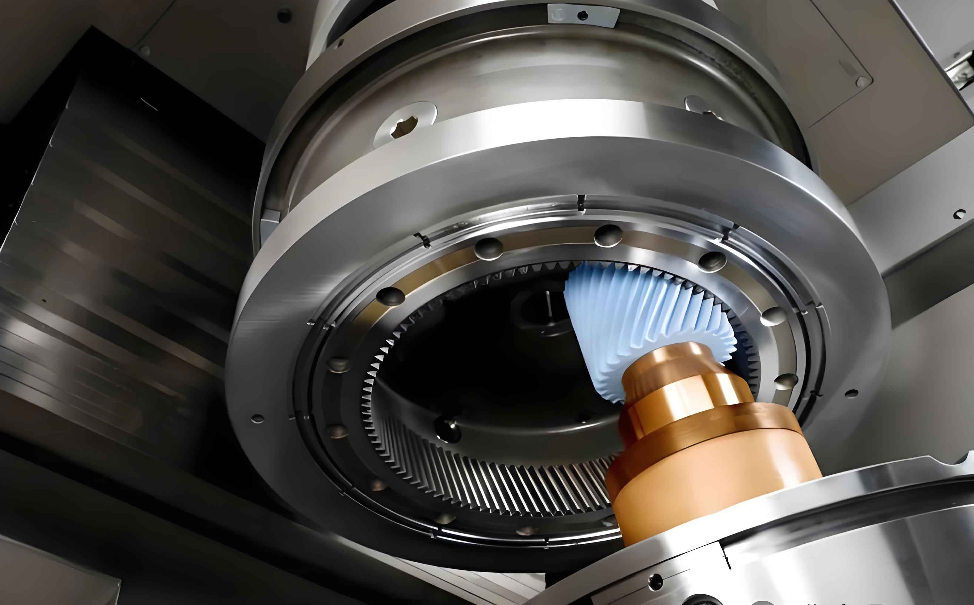
The mechanical assembly of the vibration system is critical for repeatable measurements. The system typically consists of a piezoelectric transducer, a horn (or amplitude transformer), and a tool. For the purpose of gear honing research, a conical horn design is often employed to amplify the displacement from the transducer to the tool interface. The horn must be mounted at its nodal point, where the vibrational displacement is theoretically zero, to minimize energy loss to the support structure and to allow the system to vibrate freely. In practice, a mounting flange is welded or integrally machined at this nodal location. This flange is then securely bolted to a rigid, grounded fixture or test platform. This mounting strategy is essential for stabilizing the ultrasonic gear honing system during testing and future machining operations.
For the test described, a specific charge amplifier with a known sensitivity setting was used (e.g., 0.1 mV/g, where g = 9.8 m/s²). Therefore, the sensitivity $S_a$ is 1.0×10⁻⁴ V/(m/s²). The experimental setup involves carefully bonding the accelerometer to the end-face of the horn, connecting it to the charge amplifier, and setting the amplifier’s gain appropriately. The output of the charge amplifier is connected to the oscilloscope. The ultrasonic generator’s frequency control is then used to sweep the excitation frequency while recording $V_{pp}$ and $f$ at each step.
3. Results of Resonant Frequency Characterization
Data was collected across a frequency range from approximately 14.20 kHz to 15.58 kHz. The table below summarizes a subset of the measurements, showing the driving frequency, the measured peak-to-peak voltage from the system, the calculated acceleration, and the derived displacement amplitude using the formula $A = V_{pp} / (S_a \cdot (2\pi f)^2)$, with appropriate unit conversions.
| Measurement # | Frequency, f (kHz) | Peak-Peak Voltage, Vpp (V) | Acceleration (×10⁴ m/s²) | Amplitude, A (μm) |
|---|---|---|---|---|
| 1 | 14.20 | 16.2 | 0.794 | 1.000 |
| 2 | 14.38 | 22.0 | 1.078 | 1.330 |
| 3 | 14.52 | 27.2 | 1.333 | 1.613 |
| 4 | 14.68 | 53.0 | 2.597 | 3.074 |
| 5 | 14.79 | 55.6 | 2.724 | 3.177 |
| 6 | 14.81 | 54.0 | 2.646 | 3.077 |
| 7 | 14.96 | 30.8 | 1.509 | 1.720 |
| 8 | 15.20 | 21.6 | 1.058 | 1.169 |
| 9 | 15.58 | 16.4 | 0.804 | 0.845 |
The data clearly shows a pronounced peak in vibrational amplitude. The maximum amplitude of approximately 3.18 μm occurs at a driving frequency of 14.79 kHz. Plotting amplitude versus frequency yields a classic resonance curve, which is sharply tuned. This frequency, 14.79 kHz, is therefore identified as the longitudinal resonant frequency of the assembled ultrasonic gear honing vibration system under no-load conditions. This value serves as the critical reference point for the generator’s automatic frequency tracking circuit.
4. Methodology for Vibrational Energy Assessment
Once the resonant frequency ($f_r$) is known, the system’s vibrational energy output can be characterized as a function of the electrical input power. The energy transported by the ultrasonic wave is quantified by its intensity $I$, defined as the power passing through a unit area perpendicular to the direction of propagation. For a plane progressive wave, the intensity is given by:
$$ I = \frac{1}{2} \rho c (2\pi f_r)^2 A^2 $$
where:
$I$ is the sound intensity (W/m²),
$\rho$ is the density of the horn material (kg/m³),
$c$ is the speed of sound in the horn material (m/s),
$f_r$ is the resonant frequency (Hz),
$A$ is the displacement amplitude at the measurement point (m).
This formula derives from the total energy density (kinetic + potential) in the wave multiplied by the speed of energy propagation. The total mechanical power $P_{mech}$ transmitted through the cross-section of the horn at the measurement point is the intensity multiplied by the area $S$ of that cross-section:
$$ P_{mech} = I \cdot S = \frac{1}{2} \rho c (2\pi f_r)^2 A^2 S $$
This calculated $P_{mech}$ represents the useful mechanical power available at the tool tip for the gear honing process. It is a portion of the total electrical input power $P_{elec}$ supplied by the generator, with the remainder lost to heat in the transducer, damping, and radiation.
5. Energy Measurement Results for the Gear Honing System
With the system locked at its resonant frequency (14.79 kHz), the input power level from the ultrasonic generator was incrementally increased. For each power setting, the corresponding vibration amplitude at the horn’s tip was measured using the established test system. The following table presents the recorded data, where the “Power Level” is an arbitrary or percentage setting on the generator, and the amplitude is derived from the measured $V_{pp}$.
| Test Point | Generator Power Level (%) | Peak-Peak Voltage, Vpp (V) | Amplitude, A (μm) |
|---|---|---|---|
| 1 | 80 | 3.92 | 4.899 |
| 2 | 86.4 | 4.23 | 5.292 |
| 3 | 93.6 | 4.58 | 5.732 |
| 4 | 99.7 | 4.88 | 6.106 |
| 5 | 105.4 | 5.16 | 6.455 |
| 6 | 112.1 | 5.49 | 6.865 |
To compute the mechanical power, material properties for the steel horn are assumed: density $\rho = 7800\ \text{kg/m}^3$ and longitudinal wave velocity $c = 5100\ \text{m/s}$. The cross-sectional area $S$ of the horn’s small end is a design parameter, for example, $S = 1.0 \times 10^{-4}\ \text{m}^2$ (a 10 mm diameter end). Using the formula for $P_{mech}$, the mechanical power for each amplitude reading can be calculated. The resonant frequency $f_r = 14790\ \text{Hz}$.
For Test Point 1 (A = 4.899×10⁻⁶ m):
$$ I = 0.5 \times 7800 \times 5100 \times (2\pi \times 14790)^2 \times (4.899\times10^{-6})^2 \approx 2.18 \times 10^7\ \text{W/m}^2 = 21.8\ \text{W/cm}^2 $$
$$ P_{mech} = I \times S = (2.18 \times 10^7) \times (1.0 \times 10^{-4}) \approx 2180\ \text{W} = 2.18\ \text{kW} $$
Performing this calculation for all data points yields the following relationship between measured amplitude and estimated mechanical power.
| Amplitude, A (μm) | Calculated Mechanical Power, Pmech (kW) |
|---|---|
| 4.899 | 2.18 |
| 5.292 | 2.59 |
| 5.732 | 3.04 |
| 6.106 | 3.45 |
| 6.455 | 3.85 |
| 6.865 | 4.36 |
The results demonstrate a clear, non-linear relationship between the generator’s power setting (reflected in the amplitude) and the delivered mechanical power. This relationship is crucial for developing an automatic energy control loop. By monitoring the vibration amplitude in real-time (using the accelerometer and signal processing system), the controller can infer the instantaneous mechanical power being delivered to the gear honing interface. If the load during gear honing increases, causing the amplitude to drop, the controller can command the generator to increase its electrical output to restore the desired amplitude and, hence, the desired machining power. This forms the backbone of energy auto-tuning.
6. Discussion and Implications for Advanced Gear Honing
The methodology outlined provides a robust and practical framework for characterizing ultrasonic vibration systems. The resonant frequency test is essential for initial system calibration and for setting the operating point of the frequency auto-tracking system. The ability to accurately measure displacement amplitude, and from it derive energy metrics, directly enables the implementation of energy auto-tuning.
For gear honing applications, where consistency and surface finish are paramount, maintaining optimal vibration conditions is non-negotiable. The combined frequency and energy feedback allows the ultrasonic system to adapt to changing contact conditions as the honing tool engages with the complex geometry of a gear tooth. This adaptability prevents the system from drifting out of resonance or delivering insufficient energy, which would lead to poor material removal rates, excessive tool wear, or substandard surface quality. Conversely, it also prevents over-driving the system, which could cause transducer overheating or premature fatigue failure of the horn or tool.
The proposed test system, based on a piezoelectric accelerometer and charge amplifier, offers significant advantages: it is relatively non-intrusive, has a wide frequency response suitable for ultrasonic ranges, provides a direct electrical signal for control systems, and is highly accurate when calibrated correctly. The derived formulas provide a clear mathematical link between the easily measured electrical signals (frequency and voltage) and the critical mechanical parameters (displacement amplitude and power).
Future work in this domain for ultrasonic gear honing will involve integrating this measurement and analysis chain into a closed-loop digital signal processor (DSP) or programmable logic controller (PLC). The algorithms would continuously perform the frequency sweep to track any drift in resonance due to temperature or load changes and simultaneously regulate the amplitude to a setpoint corresponding to the desired honing power. This level of control sophistication will unlock the full potential of ultrasonic-assisted gear honing, making it a more reliable, efficient, and widely adopted precision finishing technology.
In conclusion, the accurate testing of resonant frequency and vibrational energy is not merely a diagnostic step but a foundational requirement for the intelligent automation of ultrasonic systems in manufacturing. The principles and experimental techniques detailed here provide a viable pathway to achieving the stable, high-performance operation necessary for advanced ultrasonic gear honing processes, ensuring they meet the stringent demands of modern precision engineering.