
Abstract: This article focuses on the fatigue life prediction of heavy-duty spiral bevel gears. It begins with an introduction to the importance and challenges of spiral bevel gears in heavy-duty applications. The manufacturing processes and techniques are discussed in detail, including milling and grinding methods, as well as contact area inspection. Different methods for analyzing the bending and contact fatigue life are presented, such as crack initiation and propagation life predictions. The article also highlights the significance of considering various factors like material properties, gear geometry, and operating conditions for accurate fatigue life prediction.
1. Introduction
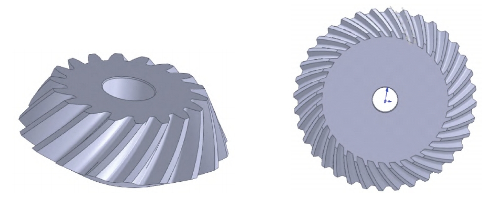
Spiral bevel gears play crucial role in many mechanical transmission systems, especially in heavy-duty applications. They are designed to transmit power between non-parallel shafts with high efficiency and reliability. However, due to the complex operating conditions and high loads they experience, fatigue failure becomes a significant concern. Predicting the fatigue life of spiral bevel gears accurately is essential for ensuring the safety and performance of the transmission systems.
1.1 Importance of Spiral Bevel Gears in Heavy-duty Applications
In heavy-duty machinery such as mining equipment, construction machinery, and large industrial drives, spiral bevel gears are often used to handle high torque and power transmission requirements. Their ability to transmit power at different angles and with relatively smooth operation makes them a preferred choice in many applications. For example, in a mining truck’s drivetrain, spiral bevel gears are responsible for transmitting the power from the engine to the wheels, enabling the vehicle to move heavy loads.
1.2 Challenges in Fatigue Life Prediction
The fatigue life prediction of spiral bevel gears is a complex task due to several factors. Firstly, the geometry of spiral bevel gears is complex, with a three-dimensional shape and non-uniform tooth loading. Secondly, the operating conditions can vary widely, including different speeds, loads, and temperatures. Thirdly, the manufacturing process can introduce variations in gear quality and residual stresses, which can affect the fatigue life. These challenges require a comprehensive understanding of the gear’s mechanical behavior and the application of advanced analysis methods.
2. Manufacturing Processes of Spiral Bevel Gears
The manufacturing process of spiral bevel gears significantly impacts their quality and performance, and thus their fatigue life. There are several key manufacturing methods and processes involved.
2.1 Milling Processing
- Tool Tilt Method and Modification Method for Active Gears: The active spiral bevel gears can be milled using the tool tilt method and the modification method. These methods require precise theoretical calculations to adjust the tool parameters and machine parameters.
- Generating Method and Forming Method for Driven Gears: For the driven spiral bevel gears, the generating method and the forming method are commonly used for milling.
- Influence on Precision: Milling is a commonly used rough processing method for spiral bevel gears. Due to factors such as processing equipment, blank material properties, and tool performance, the machining precision is generally at grade 7 or 8. It is mainly used for rough machining of the tooth grooves, leaving a machining allowance for subsequent grinding after heat treatment.
| Milling Method | Applicable Gear | Key Parameters | Precision Level |
|---|---|---|---|
| Tool Tilt Method | Active Gear | Tool Tilt Angle, etc. | 7 – 8 |
| Modification Method | Active Gear | Modification Parameters | 7 – 8 |
| Generating Method | Driven Gear | Generating Parameters | 7 – 8 |
| Forming Method | Driven Gear | Forming Parameters | 7 – 8 |
2.2 Grinding Processing
- Precision Grinding for Hard Tooth Surfaces: Grinding of spiral bevel gears is a precision machining process, typically used for hard tooth surfaces after final heat treatment. It aims to remove the deformation caused by heat treatment and milling allowances, improving the tooth surface precision.
- Double-sided and Single-sided Grinding Methods: The active spiral bevel gears are usually ground using a double-sided grinding method, where both the inner and outer sides of the cup-shaped grinding wheel grind the convex and concave tooth surfaces simultaneously. The driven spiral bevel gears are ground using a single-sided grinding method, with the inner side of the cup-shaped grinding wheel grinding the convex tooth surface and the outer side grinding the concave tooth surface separately.
- Complexity of Grinding Parameters: The grinding parameters are derived from complex calculations or software, considering factors such as grinding burns and cracks. The machining precision is generally at grade 4 or 5, which solves the interchangeability problem of spiral bevel gears.
| Grinding Method | Applicable Gear | Key Features | Precision Level |
|---|---|---|---|
| Double-sided Grinding | Active Gear | Inner and Outer Sides of Wheel | 4 – 5 |
| Single-sided Grinding | Driven Gear | Inner and Outer Sides of Wheel Separately | 4 – 5 |
2.3 Contact Area Inspection
- Importance and General Method: Contact area inspection of spiral bevel gear pairs is a crucial step in the manufacturing process. It simulates the contact situation of spiral bevel gears during operation. The general method involves mounting a pair of gears on an inspection machine, applying a coloring agent to the tooth surfaces, rolling spiral bevel gears under a given load, and observing the shape and position of the contact area while listening to the sound of gear transmission.
- Influencing Factors: This method is affected by multiple factors such as load, inspection equipment, tooling, and spiral bevel gears themselves.
| Inspection Aspect | Details |
|---|---|
| Equipment Used | Inspection Machine |
| Observation Method | Coloring Agent, Sound, and Visual Observation |
| Influencing Factors | Load, Equipment, Tooling, Gears |
3. Bending Fatigue Life Analysis of Spiral Bevel Gears
The bending fatigue life of spiral bevel gears is an important aspect to consider as it can lead to gear failure. The analysis involves predicting the crack initiation life and the crack propagation life.
3.1 Prediction of Crack Initiation Life
- Definition and Significance: Crack initiation life refers to the time from the formation of the initial crack to when the crack expands to a certain extent under fatigue load. It is a crucial part of the overall fatigue life, especially for high-strength brittle materials where a crack can cause immediate failure.
- Criteria for Initial Crack Determination: There is no unified standard for determining the initial crack. In early studies, cracks with sizes ranging from 0.05 to 0.50 mm were considered initial cracks. Later, different criteria such as 0.25 – 0.30 mm, or 0.1 – 0.2 times the edge radius of the specimen, or 2 times the Peterson steel empirical material constant were used.
- Calculation Methods: For steel, a critical crack size is formed at the end of the crack initiation stage. Considering different development mechanisms from crack initiation to expansion, calculations can be based on Dowling’s elastic fracture mechanics formula. Additionally, methods like Zheng Xiulin’s local stress-strain method can also be used to predict the crack initiation life.
| Initial Crack Criteria | Time Period | Applicable Materials |
|---|---|---|
| 0.05 – 0.50 mm | Early Studies | General |
| 0.25 – 0.30 mm, etc. | Later Studies | Steel |
3.2 Prediction of Crack Propagation Life
- Analysis Based on Linear Elastic Fracture Mechanics: Crack propagation life refers to the stage when the tooth bending fatigue crack expands from the initial size to the critical size. It can be analyzed using linear elastic fracture mechanics theory. The crack is classified into three basic types: opening type, sliding type, and tearing type. The opening type crack is the main cause of fracture in low-stress states and is the most dangerous.
- Calculation of Stress Intensity Factors: Depending on the crack type, stress intensity factors are calculated. The influence of surface hardness on fatigue life is also considered, and the crack propagation rate calculation formula is used to estimate parameters as functions of hardness values for different crack lengths.
| Crack Type | Characteristics | Stress Intensity Factor Calculation |
|---|---|---|
| Opening Type | Symmetric Opening | Based on Crack Geometry and Load |
| Sliding Type | Asymmetric Sliding | Based on Crack Geometry and Load |
| Tearing Type | Along Thickness Direction | Based on Crack Geometry and Load |
4. Contact Fatigue Life Analysis of Spiral Bevel Gears
In addition to bending fatigue, contact fatigue is also a significant factor affecting the life of spiral bevel gears.
4.1 Formation Mechanism and Characteristics of Gear Surface Contact Fatigue Cracks
- Causes of Contact Fatigue: During operation, spiral bevel gears experience repeated compressive stress due to tooth surface meshing, which can lead to fatigue spalling on the tooth surface. The high contact pressure stress in the meshing area causes maximum shear stress in the subsurface layer. When this shear stress exceeds the material’s yield strength, plastic strain occurs, leading to the formation of initial cracks.
- Characteristics of Crack Growth: The initial crack source is located below the non-reinforced layer where the ratio of maximum shear stress to surface hardness is maximum. The crack then propagates in two directions, towards the reinforced layer and inside the non-reinforced layer. Multiple main cracks may merge, resulting in spalling.
4.2 Prediction of Contact Fatigue Crack Initiation Life Based on Local N – S Method
- Local Stress – Life Curve and Initiation Standard: The local stress – life curve is used to predict the crack initiation life, with the initiation standard assuming that the fatigue crack length reaches 30 μm when the load cycle count is considered. The crack initiation point is assumed to be the point where the ratio of maximum shear stress to hardness is maximum.
- Model Based on Basquin Equation: The crack initiation life prediction is based on the Basquin equation, with the equivalent tensile stress at the initiation point’s maximum shear stress as a calculation parameter. The tensile strength limit is estimated from the local hardness.
4.3 Prediction of Contact Fatigue Crack Propagation Life Based on Fracture Mechanics
- Model Establishment and Considerations: The crack propagation life calculation model depends on the correct prediction of the crack initiation point and the crack propagation rate. The model is based on the Paris formula, with the microhardness and residual stress introduced. The local hardness value affects the crack propagation rate, and the Paris formula is revised accordingly.
- Calculation of Crack Propagation Life: The crack propagation life is obtained by integrating from the initial crack length to the final crack length within the range where the crack expands to the tooth surface.
5. Factors Affecting Fatigue Life Prediction
Several factors influence the accuracy of fatigue life prediction for spiral bevel gears.
5.1 Material Properties
- Strength and Ductility: The strength and ductility of spiral bevel gears material play a crucial role. High-strength materials may have different fatigue behaviors compared to low-strength materials. For example, brittle materials are more sensitive to crack initiation.
- Hardness: The hardness of spiral bevel gears surface affects the crack propagation rate. A higher hardness can impede crack growth, as seen in both bending and contact fatigue analyses.
5.2 Gear Geometry
- Tooth Profile: The shape of the tooth profile, including the spiral angle and tooth thickness, can influence the load distribution on the teeth. An improper tooth profile can lead to uneven loading and increased fatigue stress.
- Module and Diameter: The module and diameter of spiral bevel gears also affect its fatigue life. Larger gears may have different stress distributions compared to smaller gears.
5.2 Operating Conditions
- Load and Torque: The magnitude and variation of the load and torque applied to spiral bevel gears are important factors. Cyclic loading can accelerate fatigue crack growth.
- Speed and Temperature: The rotational speed and operating temperature can also impact the fatigue life. High speeds can cause increased dynamic loads, and temperature changes can affect the material properties.
6. Conclusion
Accurate fatigue life prediction of heavy-duty spiral bevel gears are essential for ensuring the reliability and safety of mechanical transmission systems. The manufacturing processes, including milling and grinding, have a significant impact on gear quality and fatigue life. The analysis of bending and contact fatigue, considering crack initiation and propagation, provides valuable insights into gear failure mechanisms. Factors such as material properties, gear geometry, and operating conditions must be carefully considered for reliable fatigue life prediction. Future research should focus on further improving the accuracy of prediction methods and developing more advanced manufacturing techniques to enhance the performance and durability of spiral bevel gears.