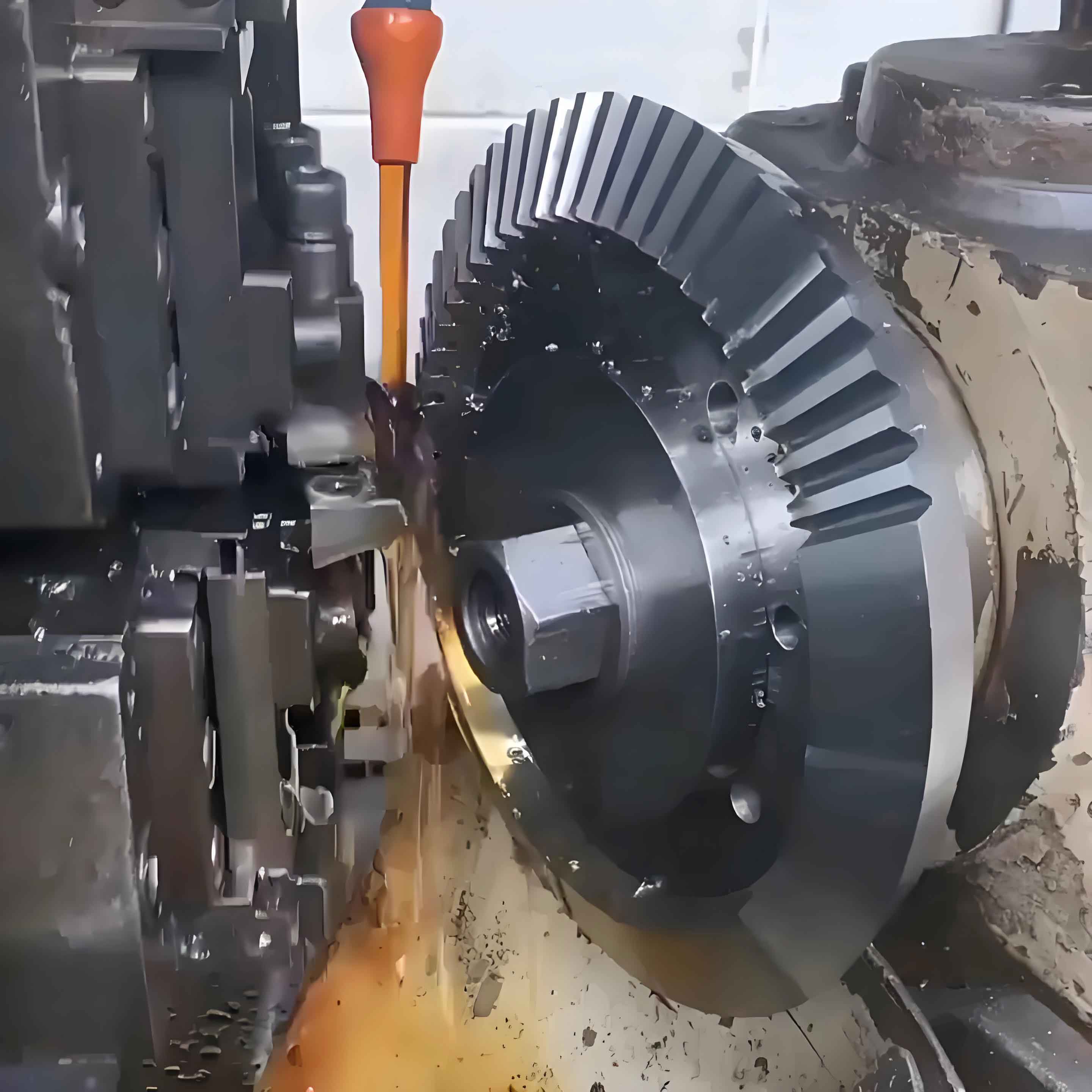
The advancement of mechanization has significantly enhanced production efficiency, quality, and operational safety across industries. Central to this evolution are gears—critical components in transmitting motion, torque, and directional force in machinery. As equipment becomes increasingly sophisticated, the demand for higher precision in gear manufacturing intensifies. This research addresses the challenge of minimizing errors in large gear production by leveraging modern Computer Numerical Control (CNC) machining, a cornerstone of contemporary gear technology. Traditional methods often result in substantial tooth profile and alignment deviations, particularly for large-module gears (module > 16 mm), which are vital in heavy industries like mining, metallurgy, and construction. This study introduces a refined CNC-based forming method, analyzing its process flow and validating its precision through empirical testing.
Large gears are predominantly manufactured using two core methodologies: the Forming Method and the Generating Method. The forming method employs profile-specific cutters to directly shape gear teeth on a blank, while the generating method relies on the kinematic engagement principle between cutter and workpiece. Key distinctions are summarized below:
| Process | Forming Method | Generating Method |
|---|---|---|
| Principle | Direct material removal using shaped tools | Simulated meshing motion between tool and workpiece |
| Advantages | Compatible with universal milling machines; flexible for low-volume production | High accuracy and efficiency for mass production |
| Disadvantages | Low efficiency (tooth-by-tooth processing); higher error susceptibility | Requires specialized CNC equipment; higher cost |
| Techniques | Gear milling, profile grinding | Gear hobbing, shaping, grinding |
This research focuses on optimizing the forming method using CNC technology. The process comprises six stages: blank forging, heat treatment, CNC machine selection, machining strategy, real-time error monitoring, and quality inspection. Each stage integrates precision-driven parameters to minimize cumulative errors.
1. Blank Forging and Heat Treatment
Material selection and initial forming are critical for structural integrity. Large gears often use alloy steels like 20CrMoTi, chosen for its balance of strength and machinability. The chemical composition is standardized as follows:
| Element | C | Mn | Si | Cr | Ti | Mo |
|---|---|---|---|---|---|---|
| Composition (%) | 0.17–0.24 | 0.40–0.70 | 0.17–0.37 | 0.80–1.10 | 0.04–0.10 | 0.15–0.25 |
Post-forging, heat treatment refines the microstructure to enhance machinability and fatigue resistance. A quenching and tempering regimen is applied:
- Quenching: 860–880°C (first and second stages), cooled in water/oil.
- Tempering: 620–650°C for >240 minutes, cooled in air/oil.
The process minimizes internal stresses and improves hardness homogeneity, crucial for subsequent machining stability. The resultant hardness ranges between 32–40 HRC.

2. CNC Machine Configuration and Parameter Optimization
CNC machine tools—equipped with Industrial PCs (IPC), motion controllers, servo drives, and high-resolution encoders—enable micron-level accuracy. Key subsystems include:
- Control Unit: IPC running real-time kinematic algorithms.
- Feedback System: Optical encoders with ±0.001 mm resolution.
- Tooling: Carbide inserts with TiAlN coating for thermal stability.
Machining parameters vary by material. For 20CrMoTi steel, optimal settings are derived from tool wear and surface finish models:
| Operation | Cutting Speed (m/min) | Feed Rate (mm/rev) | Depth of Cut (mm) |
|---|---|---|---|
| Roughing | 120–180 | 0.20 | 3.0 |
| Finishing | 160–220 | 0.10 | 0.4 |
The material removal rate (\( MRR \)) during roughing is calculated as:
$$ MRR = v_c \times f \times d \times 1000 $$
where \( v_c \) = cutting speed (m/s), \( f \) = feed rate (mm/rev), and \( d \) = depth of cut (mm). For finishing, surface roughness (\( R_a \)) follows:
$$ R_a = k \cdot \frac{f^2}{r_e} $$
where \( k \) is a material constant and \( r_e \) is the tool nose radius.
3. Hybrid Machining Strategy: Milling and Grinding
A two-stage approach combines form milling for bulk removal and profile grinding for precision finishing. Milling uses indexable disc cutters on a CAK6136c CNC mill, while grinding employs a Höfler RAPID 2000 grinder with CBN wheels. The grinding phase compensates for milling deviations using real-time data from integrated touch probes. Error compensation is modeled as:
$$ E_c = K_p \cdot e_t + K_d \cdot \frac{de_t}{dt} $$
where \( E_c \) = compensation offset, \( e_t \) = real-time error, and \( K_p \), \( K_d \) are PID control gains.
4. Validation Case Study: Large-Module Cylindrical Gear
A cylindrical gear (module = 12 mm, 24 teeth) was manufactured to validate the process. Key design parameters were:
| Parameter | Value |
|---|---|
| Pressure Angle | 20° |
| Pitch Diameter | 288 mm |
| Addendum | 12 mm |
| Dedendum | 15 mm |
Post-machining, gear quality was assessed per ISO 1328 standards. Critical tolerances include:
| Error Type | Allowable Limit (µm) | Measured Value (µm) |
|---|---|---|
| Total Profile Deviation (Fα) | 15.0 | 8.6 |
| Profile Slope Deviation (fHα) | 6.5 | 2.5 |
| Total Helix Deviation (Fβ) | 15.0 | 2.7 |
All errors fell below allowable limits, confirming the method’s efficacy. The hybrid CNC approach reduced tooth alignment errors by 82% compared to conventional forming.
5. Conclusion and Future Directions
This study demonstrates that CNC-based forming methods significantly enhance large gear accuracy. Key innovations—adaptive toolpath control, hybrid milling-grinding, and in-process error compensation—collectively minimized profile and helix deviations. Future work will extend this gear technology to helical and bevel gears, integrate AI-driven predictive maintenance for CNC systems, and explore additive-subtractive hybrid manufacturing for complex geometries. As industrial machinery evolves, refined gear manufacturing will remain pivotal in achieving higher efficiency, durability, and precision.
