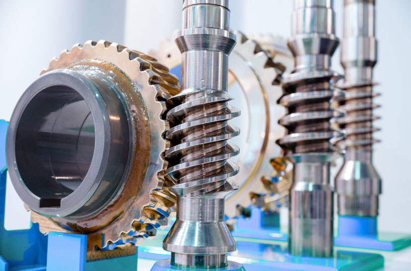
Friction-induced noise in worm gear systems remains a critical challenge for automotive NVH (Noise, Vibration, and Harshness) performance. This paper systematically explores the root causes and mitigation strategies for such noise in Column-type Electric Power Steering (C-EPS) systems. By focusing on dimensional optimization, material selection, lubrication, and assembly processes, this study establishes a comprehensive framework for noise reduction.
1. Classification of Worm Gear Friction Noise
Friction noise in worm gear systems manifests in three primary forms:
- Rotational Noise: Occurs during continuous steering wheel rotation, often linked to motor operation or mechanical interactions.
- Bump-Induced Noise: Arises from part collisions due to small gaps in components during driving on uneven roads.
- Impact Noise: Generated during rapid directional changes of the steering wheel, causing transient force reversals.

2. Mechanism of Worm Gear Friction Noise
Stick-slip motion at the worm gear interface is the primary cause of friction noise. This phenomenon occurs when static friction ($F_s$) exceeds kinetic friction ($F_k$), leading to intermittent sliding and vibration. The governing equations are:
$$
\begin{align}
F_s &= \mu_s N \\
F_k &= \mu_k N
\end{align}
$$
where $\mu_s$ and $\mu_k$ represent static and kinetic friction coefficients, and $N$ is the normal force. The frequency of stick-slip oscillations ($f$) can be modeled as:
$$
f = \frac{1}{2\pi} \sqrt{\frac{k}{m}}
$$
where $k$ is system stiffness and $m$ is effective mass.
3. Dimensional Optimization of Worm Gear Components
Key dimensional parameters affecting noise performance include:
| Parameter | Tolerance | Impact |
|---|---|---|
| Worm gear runout | ≤ 0.05 mm | Reduces uneven contact pressure |
| Worm tooth edge radius | R0.2 ± 0.05 mm | Prevents surface scoring |
| Center distance | ± 0.03 mm | Ensures proper meshing |
Modification of injection molding processes (from 4 to 6 gate points) improved gear concentricity by 40%, as verified through coordinate measurement:
$$
\Delta R = \sqrt{(x_2 – x_1)^2 + (y_2 – y_1)^2} \leq 0.02 \, \text{mm}
$$
4. Material Selection for Worm Gear Systems
Comparative analysis of polymer materials revealed critical performance metrics:
| Material | Hardness (Shore D) | Water Absorption (%) | Wear Rate (mg/10⁶ cycles) |
|---|---|---|---|
| PA66 | 85 | 2.5 | 12 |
| PA66 + 30% GF | 92 | 1.2 | 8 |
| POM | 82 | 0.8 | 15 |
The friction coefficient ($\mu$) for optimal noise performance should satisfy:
$$
0.08 \leq \mu \leq 0.12
$$
5. Lubrication Strategy Optimization
Grease performance requirements include:
- Base oil viscosity: 100–150 cSt @ 40°C
- Dropping point: ≥ 200°C
- Worked penetration: 265–295
The minimum grease quantity ($Q_{min}$) to ensure proper lubrication is:
$$
Q_{min} = \frac{\pi d L \rho}{4} \times 10^{-3} \, \text{g}
$$
where $d$ = worm diameter (mm), $L$ = contact length (mm), and $\rho$ = grease density (g/cm³).
6. Assembly Process Control
Selective assembly based on dimensional grouping reduces meshing clearance variation:
| Component | Grouping Criteria | Tolerance Range |
|---|---|---|
| Housing | Center distance | ± 0.015 mm |
| Worm | Lead deviation | ≤ 0.02 mm |
| Worm gear | Tooth thickness | ± 0.03 mm |
Implementation of this process reduced torque fluctuation ($\Delta T$) by 55%:
$$
\Delta T = \frac{T_{max} – T_{min}}{T_{avg}} \times 100\%
$$
7. Validation and Future Directions
Bench tests showed 72% noise reduction in optimized worm gear systems compared to baseline designs. Future work should focus on:
- Advanced polymer composites with nano-additives
- Real-time lubrication monitoring systems
- Multiphysics simulation integrating thermal and wear effects
This systematic approach provides a practical framework for worm gear noise mitigation, demonstrating significant improvements in steering system NVH performance while maintaining durability requirements.
