
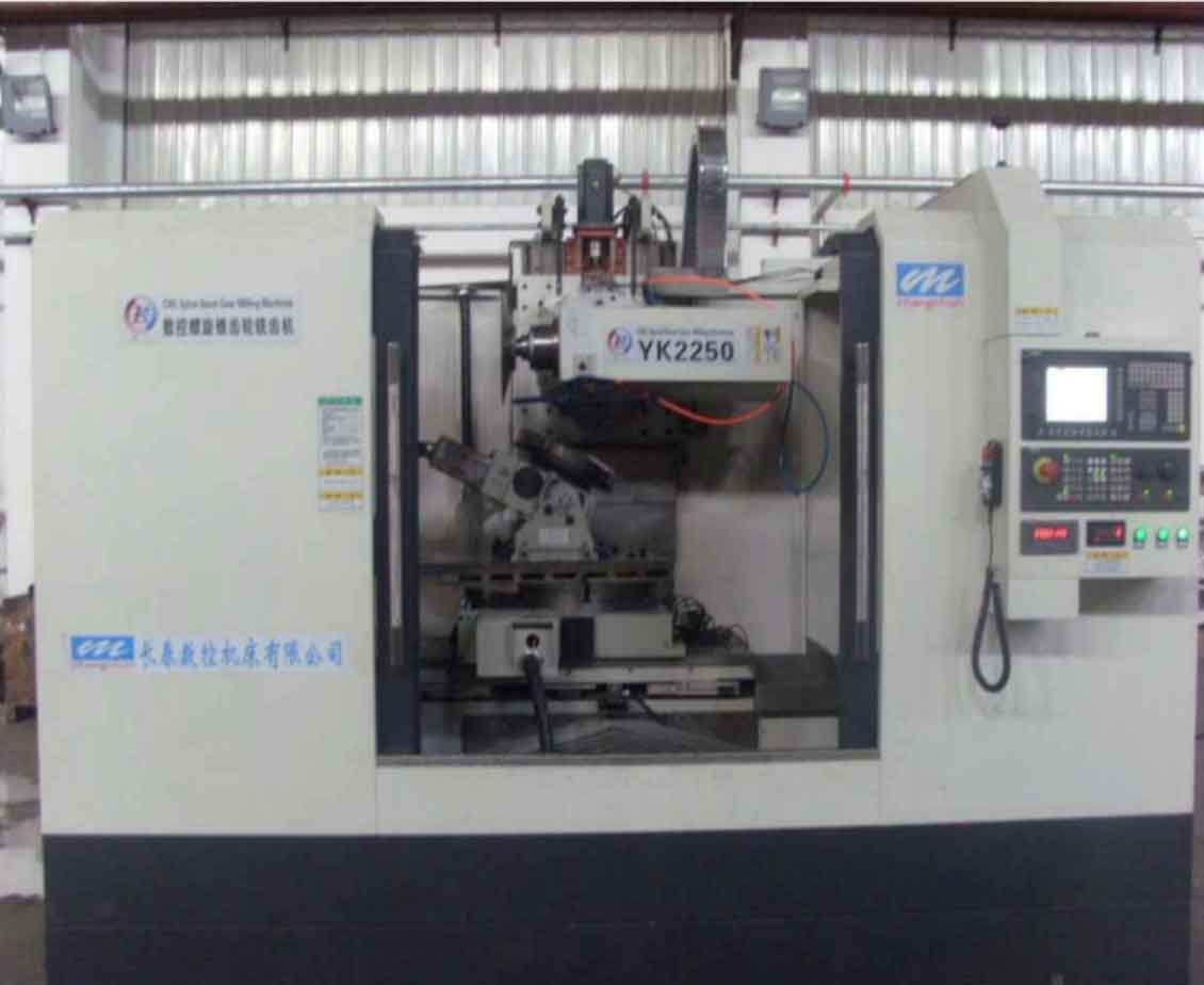
Straight bevel gears offer significant advantages over spiral bevel gears in aerospace applications due to their manufacturing maturity, lower cost, and simpler processing requirements. This study focuses on gear milling techniques using Gleason PHOENIX II CNC machines, implementing a dual-position generating method with disc-type milling cutters. The research comprehensively analyzes machining processes, measurement methodologies, and software integration to enhance quality and efficiency.
Evolution of Gear Milling Methods
Traditional straight bevel gear manufacturing primarily utilized planing machines with inherent limitations in efficiency and precision. Modern CNC gear milling solutions overcome these constraints through:
| Method | Efficiency | Precision | Crown Forming |
|---|---|---|---|
| Planing | Low (GB7 tolerance) | Moderate | Difficult |
| Twin-disc milling | Medium | GB7-GB6 | Limited |
| PHOENIX II CNC milling | High (60-90min → 12-15min) | GB6 tolerance | Precise control |
The gear milling process on PHOENIX II employs single-disc cutters in upper/lower positions with calculated negative rake angles for crown formation. The crown control equation:
$$ \delta = \frac{F_w^2 \cos\phi}{4D_u} $$
where $\delta$ = crown depth, $F_w$ = face width, $\phi$ = pressure angle, $D_u$ = cutter diameter. This enables elliptical contact patterns unattainable with conventional methods.
Tooling Systems in Gear Milling
Advanced tooling solutions significantly enhance gear milling performance:
| Tool Type | Material | Max Speed (rpm) | Life (parts/edge) |
|---|---|---|---|
| Coniflex® solid | ASP2030 (TiAlN coating) | 110 | 5-10 |
| Coniflex® Plus | Pentac® carbide inserts | 400 | 500+ |
Critical tool geometry parameters for gear milling:
$$ W_{T,max} = \frac{A_o – F_W}{A_o} \times (T_{on} – 2B_o \tan\phi) – 0.038 – S_{allowance} $$
where $W_{T,max}$ = maximum blade spacing, $A_o$ = outer cone distance, $F_W$ = face width, $T_{on}$ = mating gear toe thickness, $B_o$ = dedendum, $\phi$ = pressure angle. Proper spacing prevents toe/heel overcutting during gear milling operations.
Closed-Loop Gear Milling Process
The integrated manufacturing ecosystem for precision gear milling:
- Design: Straight Bevel [Mechanical] software generates gear data and cutter parameters
- Simulation: UNICAL analyzes contact patterns and root clearances
- Machining: PHOENIX II executes gear milling programs with real-time adaptation
- Measurement: CMMs verify geometry using GAGE-generated inspection routines
- Compensation: Measurement data automatically generates machine offsets
Contact pattern correction during gear milling follows these adjustment principles:
$$ \Delta\alpha \propto \frac{\Delta CP_h}{h_\alpha} \quad ; \quad \Delta\beta \propto \frac{\Delta CP_l}{l_\beta} $$
where $\Delta\alpha$ = pressure angle correction, $\Delta CP_h$ = contact height deviation, $h_\alpha$ = sensitivity coefficient, $\Delta\beta$ = spiral angle correction, $\Delta CP_l$ = contact length deviation.
Aerospace Application Case Study
Implementation in high-lift system angular gearboxes demonstrated gear milling advantages:
| Parameter | Conventional | Carbide Gear Milling |
|---|---|---|
| Cycle time (min) | 60-90 | 12-15 |
| Surface speed (m/min) | 55-80 | 287 |
| Profile tolerance | ±12μm | ±5μm |
| Contact pattern | Edge-concentrated | Elliptical (75% contact) |
The gear milling approach achieved consistent GB6 accuracy with crowned tooth profiles. Contact patterns showed 40% greater area coverage compared to planing methods, significantly reducing edge-loading sensitivity. Tooling costs decreased by 68% due to extended carbide insert life despite higher initial cost.
Process Optimization Techniques
Advanced gear milling strategies for aerospace components:
$$ V_c = \frac{\pi D_n N}{1000} \quad \text{(Optimal: } V_c \geq 200\text{m/min)} $$
where $V_c$ = cutting speed (m/min), $D_n$ = cutter diameter (mm), $N$ = spindle speed (rpm). High-speed gear milling requires dynamic stability analysis:
$$ f_z = \frac{v_f}{N z} \quad ; \quad \text{Stability} = \frac{k_{sys}}{\max(\text{FFT}(a_p \cdot f_z))} $$
where $f_z$ = feed per tooth (mm), $v_f$ = feed rate (mm/min), $z$ = blade count, $k_{sys}$ = system stiffness, $a_p$ = axial depth of cut.
Conclusion
CNC-based gear milling technology revolutionizes straight bevel gear manufacturing through integrated toolpath generation, precision tooling systems, and closed-loop quality control. The PHOENIX II implementation demonstrates 80% cycle time reduction while improving quality from GB7 to GB6 tolerance class. Carbide tooling enables high-speed gear milling at 400 rpm with 500+ parts per edge. Elliptical contact patterns from controlled crowning significantly enhance gear meshing performance in aerospace transmissions. Future developments will focus on AI-driven adaptive gear milling strategies and hybrid additive-subtractive processing.