
In the field of mechanical transmission, spiral bevel gears are widely used due to their high transmission quality, strong load-bearing capacity, and long service life. They are gradually replacing conventional straight bevel gears. With the continuous development of mechanical manufacturing, stricter requirements are placed on the manufacturing precision and efficiency of spiral bevel gears. To meet these demands, high-speed cutting technology, as an advanced manufacturing process, has attracted attention. High-speed cutting not only offers high cutting efficiency but also produces mechanical products with excellent quality, providing a new solution for hard tooth surface cutting of spiral bevel gears. Therefore, studying the high-speed cutting process for hard tooth surfaces of spiral bevel gears is of great significance for improving gear production levels and promoting sustainable development in mechanical manufacturing.
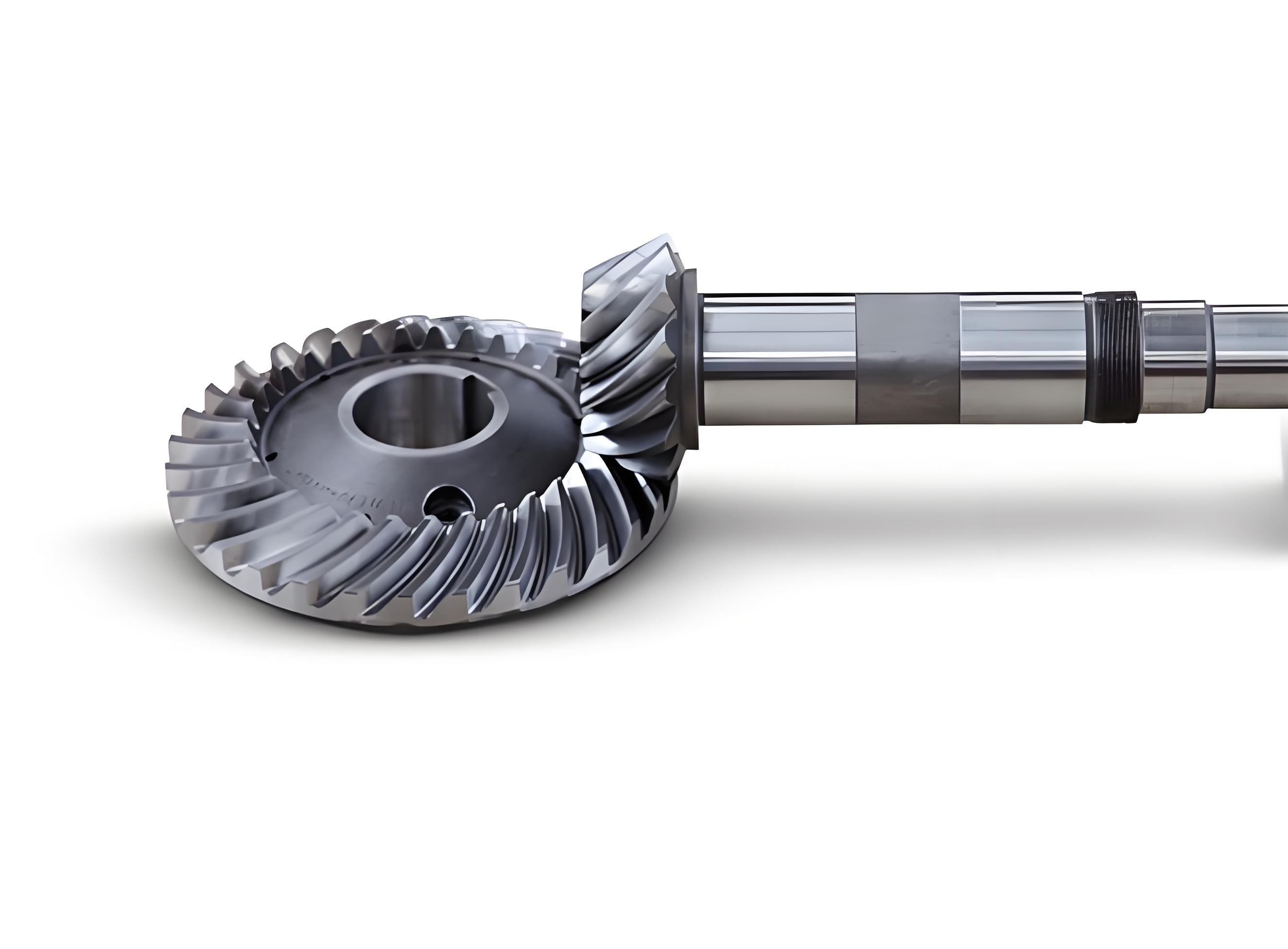
Previous research has explored aspects such as high-speed cutting performance of materials and tool design, but there is limited study on the influence of process parameters on cutting performance for spiral bevel gears. Thus, this paper focuses on investigating the impact of different process parameters on the high-speed cutting performance of hard tooth surfaces in spiral bevel gears. The essence of this process involves using tools to machine the gear tooth surfaces, and in this study, a hardened steel small spiral bevel gear is selected as the object, with a powder metallurgy high-speed steel tool employed for high-speed cutting experiments.
Experimental Design
The experimental design involves determining the gear and tool parameters. For the spiral bevel gear, a small-sized gear made of hardened steel is used, with key design parameters summarized in Table 1.
| Parameter | Unit | Value |
|---|---|---|
| Number of Teeth | – | 16 |
| Hand of Spiral | – | Left |
| Face Width | mm | 40 |
| Whole Depth | mm | 15.28 |
| Addendum | mm | 9.34 |
| Dedendum | mm | 5.94 |
| Pitch Cone Outer Diameter | mm | 500 |
| Pressure Angle | ° | 24 |
| Spiral Angle | ° | 38 |
| Pitch Cone Angle | ° | 20 |
| Face Cone Angle | ° | 25 |
For the cutting tool, a powder metallurgy high-speed steel tool is chosen due to its high purity, strength, and hardness, which offer advantages such as wear resistance and suitability for complex tool manufacturing. The tool parameters are detailed in Table 2.
| Parameter | Unit | Value |
|---|---|---|
| Tool Face Type | – | Front face: flat; Back face: relieved face |
| Cutting Edge Shape | – | Front face: curved; Back face: straight |
| Rake Angle | ° | -16 |
| Clearance Angle | ° | -18 |
| Inclination Angle | ° | -10 |
The tool is mounted on a CNC machine tool spindle with a tool holder designed for secure and easy installation. The high-speed cutting process for spiral bevel gears involves both roughing and finishing operations. In roughing, a bidirectional cutting path is used, where the tool starts from the concave side of the gear blank and moves along the circumferential direction until reaching the convex side of the next tooth, repeating until all tooth slots are machined. After heat treatment, finishing is performed using a vertical bidirectional cutting path to achieve the final tooth surface quality. The tool paths are illustrated in Figure 1, but for this text, we focus on the process parameters.
The experiment aims to study the effects of cutting force, cutting speed, and feed rate on the surface quality of hard tooth surfaces in spiral bevel gears. Surface roughness is used as a quantitative indicator of surface quality. A three-factor, six-level orthogonal experimental design is adopted, with parameters as shown in Table 3.
| Level | Cutting Force (N) | Cutting Speed (m/min) | Feed Rate (mm/r) |
|---|---|---|---|
| 1 | 200 | 400 | 1.5 |
| 2 | 250 | 500 | 2.0 |
| 3 | 300 | 600 | 2.5 |
| 4 | 350 | 700 | 3.0 |
| 5 | 400 | 800 | 3.5 |
| 6 | 450 | 900 | 4.0 |
The cutting process is performed on a CNC machine, and after machining, the surface roughness of the hard tooth surface is measured using a surface roughness tester at multiple random locations, with the average value taken as the result. The relationship between process parameters and surface quality is analyzed to evaluate cutting precision for spiral bevel gears.
Theoretical Background and Formulas
In high-speed cutting of spiral bevel gears, the surface roughness (Ra) can be modeled as a function of cutting force (F), cutting speed (V), and feed rate (f). Based on empirical studies, a general relationship can be expressed using a polynomial equation. For instance, the surface roughness might be approximated by:
$$ R_a = k_0 + k_1 F + k_2 V + k_3 f + k_4 F^2 + k_5 V^2 + k_6 f^2 + k_7 F V + k_8 F f + k_9 V f $$
where \( k_0, k_1, \ldots, k_9 \) are coefficients determined through regression analysis. This equation accounts for linear and interaction effects of the parameters on the surface quality of spiral bevel gears. For hardened steel materials, the cutting force can be related to material properties and tool geometry using:
$$ F = K_s \cdot a_p \cdot f \cdot \sin(\theta) $$
where \( K_s \) is the specific cutting force, \( a_p \) is the depth of cut, \( f \) is the feed rate, and \( \theta \) is the tool approach angle. In the context of spiral bevel gears, these parameters are adjusted based on gear geometry and tool path.
The cutting speed for high-speed machining of hardened steel spiral bevel gears typically exceeds 380 m/min, as per the Salomon hypothesis. The effect of cutting speed on surface roughness can be described by an exponential decay model in optimal ranges:
$$ R_a \propto V^{-\alpha} \quad \text{for} \quad V < V_{opt} $$
where \( \alpha \) is a positive constant and \( V_{opt} \) is the optimal cutting speed. Beyond \( V_{opt} \), vibrations and thermal effects may increase roughness.
Experimental Results and Analysis
The experimental results show the influence of cutting force, cutting speed, and feed rate on the surface roughness of hard tooth surfaces in spiral bevel gears. The data are summarized in Table 4, which presents average surface roughness values for different parameter combinations.
| Cutting Force (N) | Cutting Speed (m/min) | Feed Rate (mm/r) | Surface Roughness Ra (μm) |
|---|---|---|---|
| 200 | 500 | 1.5 | 0.85 |
| 250 | 500 | 1.5 | 0.63 |
| 300 | 500 | 1.5 | 0.70 |
| 350 | 500 | 1.5 | 0.78 |
| 400 | 500 | 1.5 | 0.90 |
| 450 | 500 | 1.5 | 1.05 |
| 250 | 400 | 1.5 | 0.80 |
| 250 | 600 | 1.5 | 0.68 |
| 250 | 700 | 1.5 | 0.71 |
| 250 | 800 | 1.5 | 0.75 |
| 250 | 900 | 1.5 | 0.88 |
| 250 | 700 | 2.0 | 0.78 |
| 250 | 700 | 2.5 | 0.85 |
| 250 | 700 | 3.0 | 0.92 |
| 250 | 700 | 3.5 | 1.10 |
| 250 | 700 | 4.0 | 1.25 |
From the data, we can derive trends for each parameter. For cutting force, with constant cutting speed and feed rate, the surface roughness of spiral bevel gears decreases initially and then increases as cutting force rises. This can be modeled by a quadratic function:
$$ R_a(F) = a F^2 + b F + c $$
where \( a > 0 \), indicating a convex parabola. For example, from levels 1 to 6 in Table 4, the minimum roughness occurs at F = 250 N. This is because insufficient cutting force leads to poor material removal, while excessive force causes deformation and increased friction on the hard tooth surface of spiral bevel gears.
For cutting speed, with constant cutting force and feed rate, the surface roughness also shows a U-shaped trend, decreasing first and then increasing. The optimal cutting speed is around 700 m/min for the spiral bevel gears tested. This relationship can be expressed as:
$$ R_a(V) = d V^2 + e V + g $$
with \( d > 0 \). At low speeds, prolonged tool-workpiece contact increases friction; at high speeds, vibrations and thermal effects degrade surface quality.
For feed rate, with constant cutting force and speed, the surface roughness increases monotonically with feed rate. This linear relationship can be approximated by:
$$ R_a(f) = h f + i $$
where \( h > 0 \). Higher feed rates lead to greater tool engagement and heat generation, causing oxidation and burning on the hard tooth surface of spiral bevel gears.
To synthesize these effects, a multiple regression model can be developed. Using the data from Table 4, we can estimate coefficients for the polynomial equation mentioned earlier. For instance, a simplified version for spiral bevel gears might be:
$$ R_a = 1.2 – 0.005F + 0.0001V + 0.2f + 0.00001F^2 – 0.000001V^2 + 0.05f^2 + \epsilon $$
where \( \epsilon \) represents error terms. This model highlights the complex interactions in high-speed cutting of spiral bevel gears.
Discussion on Optimization
Based on the results, the optimal cutting parameters for high-speed cutting of hard tooth surfaces in spiral bevel gears are identified as: cutting force of 250 N, cutting speed of 700 m/min, and feed rate of 1.5 mm/r. This combination yields the lowest surface roughness, indicating high cutting precision. The importance of parameter selection is emphasized for improving the manufacturing quality of spiral bevel gears.
Furthermore, the study suggests that tool performance, including material and geometric parameters, also plays a critical role. Future research should explore the relationship between tool surface properties and high-speed cutting performance for spiral bevel gears. This could involve testing different tool coatings or advanced materials like cubic boron nitride (CBN) for enhanced durability.
In practical applications, such as in aerospace or automotive industries, the high-speed cutting process for spiral bevel gears can significantly reduce production time and improve gear performance. By optimizing parameters, manufacturers can achieve better surface integrity and longer service life for spiral bevel gears.
Conclusion
This research investigates the high-speed cutting process for hard tooth surfaces of spiral bevel gears, focusing on the effects of cutting force, cutting speed, and feed rate. The experimental results show that surface roughness, as a measure of cutting precision, varies with these parameters: it first decreases and then increases with cutting force, similarly with cutting speed, and increases monotonically with feed rate. The optimal parameters for the tested spiral bevel gears are a cutting force of 250 N, cutting speed of 700 m/min, and feed rate of 1.5 mm/r, which minimize surface roughness and enhance cutting accuracy.
The findings provide valuable guidance for improving the high-speed cutting process of spiral bevel gears in industrial settings. However, limitations exist, such as the focus only on process parameters without considering tool variations. Future work should examine tool-related factors and their interactions with cutting parameters to further advance the manufacturing of spiral bevel gears. This research contributes to the development of efficient and precise gear production techniques, supporting innovation in mechanical transmission systems.