
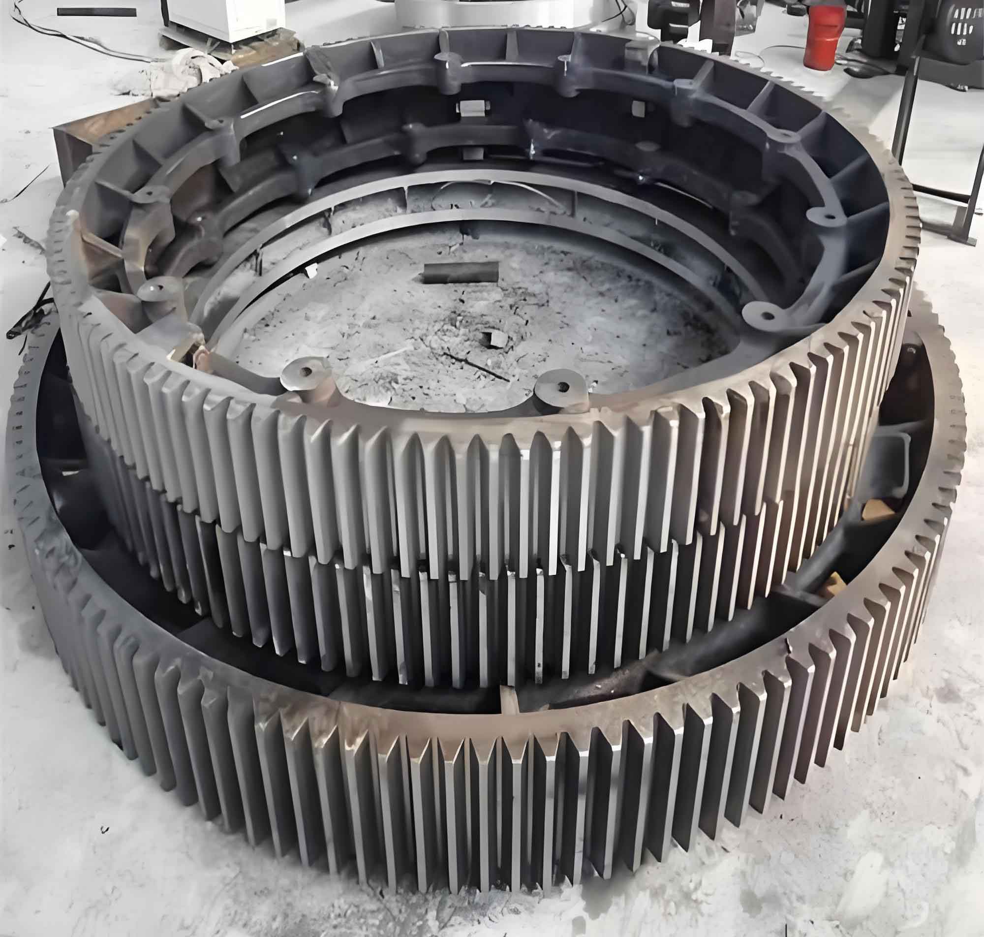
Oversize straight bevel gears are critical components in large-scale industrial equipment, where manufacturing precision significantly impacts operational stability. For split-structure large gears, accuracy primarily depends on individual segment machining precision. Structural deformation after tooth cutting is the main factor affecting accuracy, accounting for 92.2% of total deformation according to existing research. This study establishes a stiffness-stress-deformation mapping model to predict deformation during machining.
Stiffness Evolution During Machining
The stiffness of large gear blanks continuously decreases during cutting. Using bending strain energy equivalence, we model split blanks as equivalent beams. The equivalent stiffness \(K\) is calculated as:
$$K = \frac{EI}{L}$$
where \(E\) is elastic modulus, \(I\) is moment of inertia, and \(L\) is blank length. For variable cross-section blanks, stiffness is solved through energy equivalence equations:
$$U_1 = U_2$$
$$\int_0^L \frac{1}{2} EI_1 (y”(x))^2 dx = \int_0^L \frac{1}{2} EI_2 (y”(x))^2 dx$$
Stiffness variation under different processing sequences shows accelerated reduction when cutting central teeth:
| Material Removal State | Stiffness (10⁵ N/m) |
|---|---|
| Unprocessed | 8.998 |
| Tooth groove 1 removed | 8.973 |
| Tooth groove 4 removed | 7.808 |
| Tooth grooves 1-2 removed | 8.665 |
| Tooth grooves 4-5 removed | 6.699 |
| Tooth grooves 1-3 removed | 7.358 |
Stress Evolution in Cutting Process
Initial residual stresses in 7075-T7451 aluminum alloy blanks follow M-shaped distributions through thickness. X-direction stresses dominate deformation, with surface compressive stresses reaching -17.21 MPa and internal tensile stresses peaking at 16.21 MPa. ABAQUS simulations with SIGINI subroutines reveal stress redistribution patterns:
$$\sigma_x = \sum_{i=1}^{5} [a_i \cos(0.08(i+2)z) + b_i \sin(0.08(i+2)z)]$$
Post-machining stress characteristics include:
- Compressive stress (-15 MPa) at tooth groove bottoms
- Tensile stress release at non-cutting zones
- Y-direction stress changes concentrated at surfaces
Deformation Analysis
Finite element analysis shows bending deformation dominates, with maximum Z-direction displacement occurring at blank centers. Deformation increases exponentially when blank thickness falls below critical thresholds:
$$f = k_1 e^{-k_2 t} + k_3$$
where \(t\) is thickness-to-tooth-height ratio. Critical thickness thresholds are:
| t | Deformation (mm) |
|---|---|
| 1.2 | 0.265 |
| 1.8 | 0.136 |
| 2.2 | 0.078 |
| 3.0 | 0.045 |
Deformation mapping models combine stiffness variation and stress redistribution. The additional bending moment during material removal is:
$$M = \int_0^{z_1} \sigma(z)(h – z – z_c) \cdot [L – 2(x_1 + x_2 – x_3 \cdot z/2.25m)] dz$$
Deformation calculation uses moment-area method integration:
$$\Delta = \int_A^B \frac{M x}{EI} dx$$
Experimental Verification
CNC machining tests on YK3140 machines measured deformations via coordinate measuring:
| Processing Stage | Max Z-deformation (mm) |
|---|---|
| Central tooth groove | 0.058 |
| Right half completed | 0.097 |
| Full processing | 0.137 |
Geometric accuracy changes included:
- End face angle reduction: 36.009° → 35.989°
- Outer diameter increase: 1200.001mm → 1200.072mm
- Flatness tolerance increase: 0.038mm → 0.161mm
Experimental results showed 96.4% consistency with simulation predictions, validating both FEA and theoretical models.
Design Parameter Optimization
Parametric studies reveal optimal design principles for large gears:
- Thickness: Minimum deformation at t=1.8 (thickness-to-tooth-height ratio)
- Segment proportion: 5-8 teeth per segment balances deformation and assembly complexity
- Processing sequence: Central-to-peripheral cutting reduces maximum deformation by 18.7%
Deformation increases exponentially when segment tooth counts exceed 8:
$$f = 0.0215n^{2.34} \quad (n > 8)$$
where \(n\) is number of teeth per segment.
Conclusion
This research establishes a stiffness-stress-deformation mapping model for large gear machining deformation prediction. Key findings include:
- Stiffness decreases nonlinearly during cutting, accelerating when processing central regions
- X-direction stress redistribution dominates bending deformation
- Optimal thickness is 1.8× tooth height with 5-8 teeth per segment
- Central-to-edge processing sequence minimizes deformation
The models achieve 96.4% prediction accuracy, providing theoretical foundations for precision manufacturing of large gears. Future work will focus on assembly error compensation and multi-segment coupling mechanisms.