
Helical gears are critical components in mechanical transmission systems, prized for their high load-bearing capacity, durability, smooth operation, low noise, and minimal vibration. These attributes make them indispensable in heavy-duty applications like mining, marine engineering, and aerospace. Gear shaving stands out as an economical and highly efficient finishing method for achieving superior precision and surface quality in helical gear production. This process utilizes a shaving cutter, essentially a helical gear with serrated cutting edges on its flanks. This analysis focuses specifically on the axial gear shaving process and its dynamic characteristics.
Principle of Axial Gear Shaving
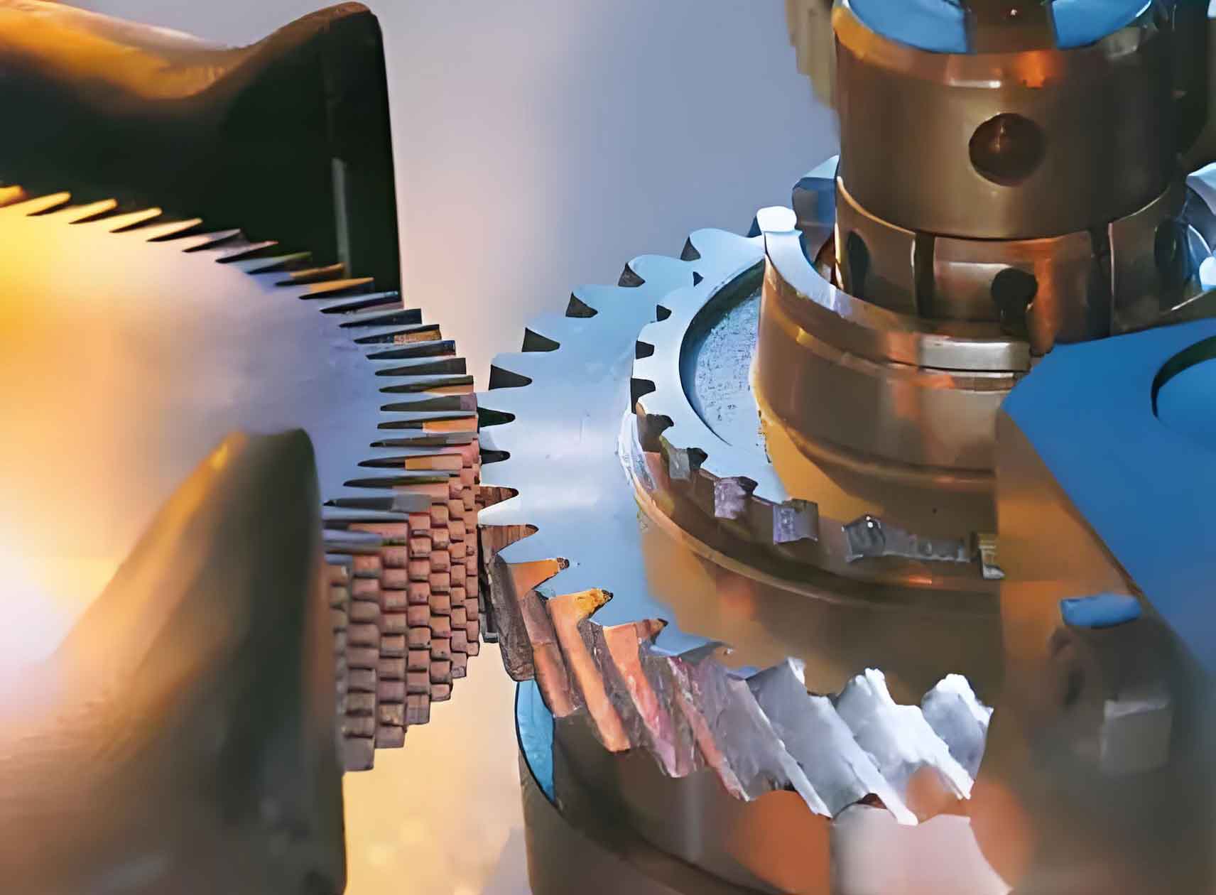
During axial gear shaving, a specific spatial relationship exists between the workpiece helical gear and the shaving cutter. Their rotational axes intersect at an angle known as the shaft intersection angle (\(\alpha\)), as illustrated in the figure below. This angle is dynamic, varying based on the machining position and depth to ensure optimal contact and cutting action throughout the process. Precise control of this angle and other associated parameters is paramount for achieving high transmission accuracy in the finished gear.
The shaft intersection angle (\(\alpha\)) is fundamentally determined by the difference in the helix angles of the gear (\(\beta_g\)) and the cutter (\(\beta_c\)):
$$\alpha = \beta_g – \beta_c$$
The relative motion can be summarized as:
1. The shaving cutter rotates about its own axis (\( \omega_c \)).
2. The shaving cutter simultaneously translates along the axis of the workpiece gear (\( V_a \)).
3. The workpiece helical gear rotates about its own axis (\( \omega_g \)).
The combined rotary and translatory motions, coupled with the applied shaving force, enable the cutter to progressively remove material and generate the final gear tooth flank geometry. Axial gear shaving is particularly advantageous for machining wide-faced gears because the feed motion is parallel to the gear axis, eliminating the need for radial cutter movement.
Analysis of Axial Gear Shaving Process Parameters
To maintain cutting efficiency and precision throughout the tool’s life, the shaving cutter undergoes multiple regrinds, typically between 4 and 10 times. Each regrind alters the cutter’s geometry, necessitating adjustments in process parameters to compensate. The cutter used in this study had the following specifications:
- Number of Teeth: 43
- Normal Module: 4.25 mm
- Normal Pressure Angle: 20°
- Helix Angle: 15°
- Normal Tooth Thickness at Pitch Diameter (New): 6.579 mm
- Normal Tooth Thickness at Pitch Diameter (Final Regrind): 6.079 mm
- Tip Diameter (New): 197.7 mm
- Tip Diameter (Final Regrind): 195.961 mm
The impact of successive cutter regrinds on key geometric parameters of both the cutter and the workpiece gear is significant. Table 1 details how the effective profile diameters change with regrinding cycles.
| Regrind State | Cutter Effective Profile Start Diameter (mm) | Cutter Effective Profile End Diameter (mm) | Required Cutter Effective Profile End Diameter (mm) | Workgear Effective Profile Start Diameter (mm) | Workgear Effective Profile Root Diameter (mm) | Workgear Effective Profile End Diameter (mm) |
|---|---|---|---|---|---|---|
| New Cutter | 206.898 | 196.160 | 206.898 | 84.775 | 84.539 | 100.150 |
| 1st Regrind | 206.512 | 195.982 | 206.512 | 84.775 | 84.539 | 100.150 |
| 2nd Regrind | 206.122 | 195.808 | 206.122 | 84.775 | 84.539 | 100.150 |
| 3rd Regrind | 205.728 | 195.634 | 205.728 | 84.775 | 84.539 | 100.150 |
| 4th Regrind | 205.328 | 195.463 | 205.328 | 84.775 | 84.539 | 100.150 |
| Final Regrind | 204.924 | 195.294 | 204.924 | 84.775 | 84.539 | 100.150 |
Table 1 clearly shows that as the number of regrinds increases, the effective profile diameters of the shaving cutter (start, end, and required end diameters) progressively decrease. In contrast, the effective profile diameters of the workpiece gear (start, root, and end diameters) remain constant. This stability in the workpiece dimensions highlights the need for adjustments in meshing parameters to maintain accuracy despite the changing cutter geometry.
Table 2 presents the corresponding adjustments required in meshing parameters – workgear normal tooth thickness at pitch diameter, center distance, and shaft intersection angle – across the same regrinding cycles.
| Regrind State | Workgear Normal Tooth Thickness at Pitch Diameter (mm) | Center Distance (mm) | Shaft Intersection Angle (°) |
|---|---|---|---|
| New Cutter | 6.579 | 158.465 | 15.0109 |
| 1st Regrind | 6.479 | 158.328 | 14.9981 |
| 2nd Regrind | 6.379 | 158.190 | 14.9853 |
| 3rd Regrind | 6.279 | 158.051 | 14.9724 |
| 4th Regrind | 6.179 | 157.912 | 14.9594 |
| Final Regrind | 6.079 | 157.771 | 14.9463 |
The data in Table 2 reveals a consistent trend: as the cutter is reground, the workgear normal tooth thickness at the pitch diameter, the center distance between gear and cutter, and the shaft intersection angle all decrease progressively. These precise, incremental adjustments are crucial during the axial gear shaving process. They ensure the instantaneous positional coordinates of the shaving cutter accurately match the theoretical coordinates required for the workpiece gear throughout its profile, leading to superior gear quality and transmission performance. The necessity for such fine-tuning underscores the complexity of achieving high precision in axial gear shaving operations.
Dynamic Characteristics of Axial Gear Shaving
Understanding the dynamic behavior of the gear shaving process is essential for optimizing performance, minimizing vibration and noise, and maximizing tool life. Simulation analysis provides insights into how key dynamic parameters evolve during the cutting engagement cycle, characterized by the roll angle (\(\theta\)).
Shaving Force
The force exerted on the shaving cutter is a primary dynamic characteristic. Figure 1 illustrates the variation of shaving force (\(F\)) with increasing roll angle (\(\theta\)) during the axial gear shaving process.
Figure 1: Shaving Cutter Force vs. Roll Angle
$$F(\theta) = F_0 \cdot \sin\left(\frac{2\pi\theta}{\theta_p}\right) + F_m$$
Where \(F_0\) is the force amplitude, \(\theta_p\) is the angular pitch, and \(F_m\) is a mean force component. The force exhibits a distinct periodic fluctuation pattern. It alternates cyclically between positive and negative directions corresponding to the cutting action on the driving and driven flanks of the gear teeth. The magnitude of the force generally increases initially as engagement deepens but shows a complex interaction pattern throughout the roll angle. The cyclic nature of the force is directly linked to the alternating meshing conditions on the opposite tooth flanks inherent in the gear shaving kinematics.
Cutter Velocity and Acceleration
The translational velocity (\(V_a\)) and acceleration (\(a_c\)) of the shaving cutter along the gear axis are critical for chip formation and surface generation. Figure 2 depicts how these parameters vary with the roll angle.
Figure 2: Shaving Cutter Velocity & Acceleration vs. Roll Angle
The cutter velocity (\(V_a\)) follows a generally parabolic trend relative to the roll angle:
$$V_a(\theta) \approx k_v \cdot \theta \cdot (\theta_{max} – \theta)$$
where \(k_v\) is a velocity constant and \(\theta_{max}\) is the maximum roll angle considered. Velocity starts low, increases to a maximum value near the mid-point of the engagement cycle (\(\theta \approx 15-20^\circ\)), and then decreases as the roll angle progresses further.
Cutter acceleration (\(a_c\)), being the derivative of velocity, exhibits a corresponding trend:
$$a_c(\theta) = \frac{dV_a}{d\theta} \approx k_v \cdot (\theta_{max} – 2\theta)$$
Acceleration is highest at the beginning of the cut (\(\theta \approx 0-10^\circ\)), decreases linearly, crosses zero around the velocity maximum point (\(\theta \approx 15-20^\circ\)), and becomes negative (deceleration) during the latter part of the engagement cycle (\(\theta > 20^\circ\)). This characteristic acceleration profile, particularly the initial peak, contributes significantly to the dynamic loads on the cutter and the gear shaving system, influencing vibration levels.
Conclusion
This investigation into axial gear shaving for helical gears provides valuable insights into the process mechanics and dynamics. The key findings are:
- Progressive Cutter Wear & Parameter Adjustment: Multiple regrinds of the shaving cutter are necessary during its lifespan. Each regrind reduces the cutter’s effective profile diameters (start, end, required end). To compensate and maintain high-precision gear shaving, critical meshing parameters – workgear normal tooth thickness at the pitch diameter, center distance, and shaft intersection angle – must be decreased incrementally. This fine-tuning ensures continuous accurate coordination between the cutter position and the required workpiece geometry.
- Dynamic Parameter Variation: The axial gear shaving process exhibits significant dynamic variations throughout the gear tooth engagement cycle (roll angle):
- Shaving Force: The force on the cutter shows periodic, alternating fluctuations due to the changing contact conditions on the driving and driven tooth flanks.
- Cutter Velocity: The translational velocity of the cutter along the gear axis follows an approximate parabolic path, starting low, peaking near the middle of the engagement, and decreasing towards the end.
- Cutter Acceleration: Acceleration is highest at the start of engagement, decreases linearly, becomes zero near peak velocity, and turns negative (deceleration) in the latter half of the cycle. This peak acceleration contributes to dynamic loads and potential vibration.
Understanding these geometric dependencies and dynamic characteristics is fundamental for optimizing the axial gear shaving process. It enables better prediction and control of cutting forces, leading to improved gear quality, extended cutter life through optimized regrinding and parameter adjustment strategies, and reduction in vibration and noise by managing the inherent dynamic fluctuations. This knowledge provides crucial theoretical support and technical guidance for enhancing the efficiency and precision of helical gear manufacturing via axial gear shaving.