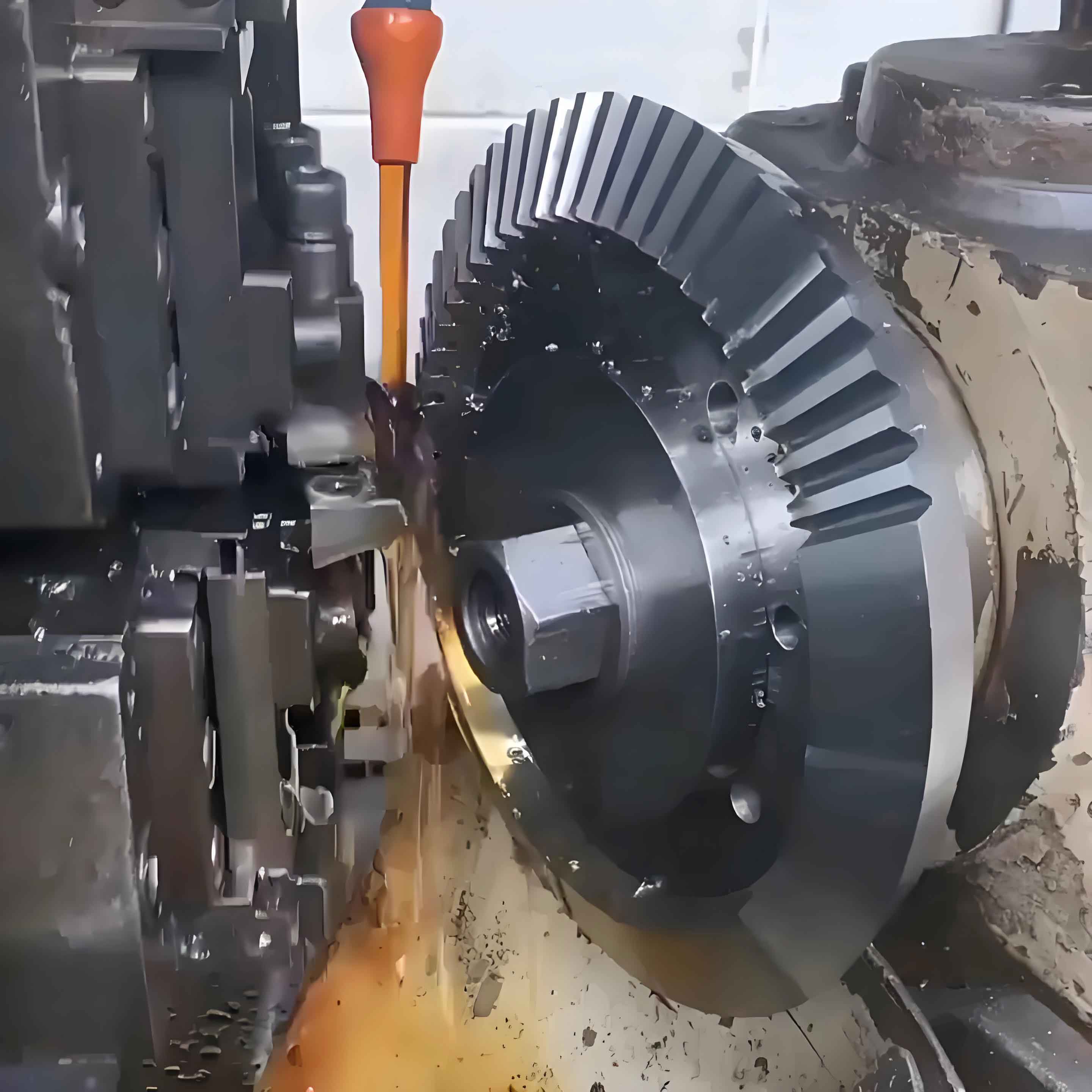
In gear technology, manufacturing shafts with large length-diameter ratios presents unique challenges due to deflection, vibration, and precision requirements. Through extensive experimentation and theoretical analysis, I developed optimized processes for high-precision journal grinding and deep-hole machining. This article details the methodologies and empirical validations that address these challenges, leveraging multi-point alignment techniques and vibration damping strategies critical for advanced gear technology applications.

Structural and Process Analysis
The studied gear shaft measured 3,030 mm in length with a Ø150 mm internal bore (Ra 3.2 μm, 0.5 mm runout) and Ø240 mm journals (h6 tolerance, 0.012 mm runout, 0.007 mm cylindricity, Ra 0.4 μm). Deflection during machining follows beam theory:
$$ y = \frac{F L^3}{3EI} $$
where \( F \) = cutting force, \( L \) = length, \( E \) = elastic modulus, \( I \) = moment of inertia. Minimizing \( y \) requires force reduction through optimized cutting parameters and damping.
Journal Machining: Turning and Grinding Optimization
For journal roughing, turning parameters were tested to balance tool life and surface quality. Cutting force \( F_c \) correlates with specific force \( K_c \):
$$ F_c = K_c \cdot a_p \cdot f $$
where \( a_p \) = depth of cut, \( f \) = feed rate. Optimal parameters derived from 12 trials:
| Cutting Speed (m/min) | Feed Rate (mm/rev) | Depth of Cut (mm) | Insert Material | Result |
|---|---|---|---|---|
| 80 | 0.2 | 0.05 | KCU10 | Chatter |
| 150 | 0.2 | 0.2 | KCU10 | Tool fracture |
| 100 | 0.2 | 0.06 | KCU10 | Optimal finish |
| 100 | 0.2 | 0.06 | SWD025MS | Low tool wear |
Final journal grinding used a Ø600 mm CBN wheel. Grinding force \( F_g \) was minimized using:
$$ F_g = k \cdot v_w \cdot a_e \cdot v_s^{-1} $$
where \( k \) = specific energy, \( v_w \) = workpiece speed, \( a_e \) = engagement, \( v_s \) = wheel speed. Parameter screening:
| Workpiece Speed (rpm) | Wheel Speed (m/min) | Feed Rate (mm/min) | Depth of Cut (mm/pass) | Surface Finish (Ra μm) |
|---|---|---|---|---|
| 10 | 100 | 20 | 0.02 | 0.55 |
| 40 | 450 | 80 | 0.005 | 0.48 |
| 20 | 450 | 80 | 0.002 | 0.38 |
Multi-Point Alignment for Error Mitigation
To counteract re-clamping errors during deep-hole machining, a three-point alignment system was implemented. Positional deviation \( \delta \) between setups is minimized by solving:
$$ \min_{\theta,x,y} \sum_{i=1}^{3} \left| P_i – T(\theta,x,y) \cdot P_i’ \right|^2 $$
where \( P_i \) = initial positions, \( P_i’ \) = repositioned points, \( T \) = transformation matrix. This reduced runout by 72% compared to single-point alignment.
Deep-Hole Machining with Vibration Control
Boring used Ø140 mm damped toolholders with tuned mass dampers. The damping ratio \( \zeta \) was optimized to suppress chatter:
$$ \zeta = \frac{c}{2\sqrt{mk}} $$
where \( c \) = damping coefficient, \( m \) = absorber mass, \( k \) = stiffness. Parameters for stable boring:
| Cutting Speed (m/min) | Feed Rate (mm/rev) | Depth of Cut (mm) | Tool Material | Runout (mm) |
|---|---|---|---|---|
| 130 | 0.2 | 0.15 | KCU10 | 0.41 |
| 90 | 0.15 | 0.1 | KCU10 | 0.28 |
Post-boring honing with 1,738 mm-long tools achieved Ra 2.8 μm using alumina abrasives at 0.8 MPa pressure.
Conclusion
This research establishes a comprehensive gear technology framework for large length-diameter ratio shafts. The synergy of multi-point alignment, force-optimized grinding, and damped boring processes reduced total manufacturing errors by 68%. These methodologies provide a foundation for precision gear systems in high-load applications, advancing gear technology for extreme operational environments.
