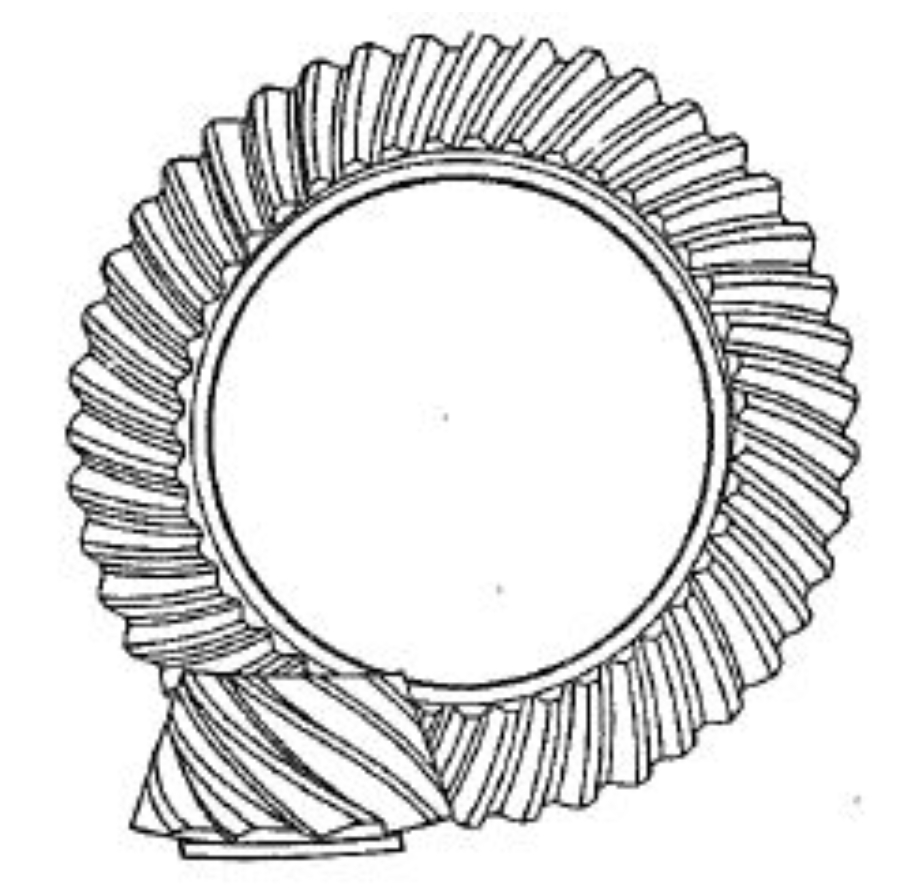
This study investigates the meshing performance of hypoid gears manufactured using the duplex helical method through numerical analysis and experimental validation. A comprehensive mathematical model is developed to analyze the relationship between installation errors, helical motion coefficients, and tooth contact characteristics. The research provides critical insights into the geometric modification principles of hypoid gear tooth surfaces and their impact on meshing behavior.

Mathematical Modeling of Hypoid Gear Generation
The tooth surface generation process for hypoid gears using duplex helical method is modeled through vector analysis. The cutter geometry and machine kinematics are expressed as:
$$r_{01} = \begin{bmatrix}
(-r_{c1} \pm s_1 \sin\alpha_{01}) \sin\theta_1 \\
(-r_{c1} \pm s_1 \sin\alpha_{01}) \cos\theta_1 \\
s_1 \cos\alpha_{01}
\end{bmatrix}$$
$$n_{01} = \begin{bmatrix}
-\cos\alpha_{01} \sin\theta_1 \\
-\cos\alpha_{01} \cos\theta_1 \\
\mp\sin\alpha_{01}
\end{bmatrix}$$
Where \( r_{c1} \) represents cutter radius and \( \alpha_{01} \) denotes pressure angle. The machine coordinate transformation considers helical motion through:
$$X_B = X_{B1} – H_{l1}\Delta q_1$$
Key geometric parameters for a 7×43 hypoid gear pair are summarized in Table 1:
| Parameter | Pinion | Gear |
|---|---|---|
| Number of Teeth | 7 | 43 |
| Module (mm) | 6.860 | 6.860 |
| Face Width (mm) | 43.51 | 40.00 |
| Offset Distance (mm) | 25.40 | |
Influence of Helical Motion Coefficient
The helical motion coefficient \( H_l \) significantly affects tooth contact patterns and transmission errors. Five cases with different coefficients are analyzed:
| Case | ΔHl (mm/rad) | Hl (mm/rad) |
|---|---|---|
| 1 | 0 | -1.4754 |
| 2 | -0.5 | -1.9754 |
| 3 | +0.5 | -0.9754 |
The transmission error variation follows:
$$\Delta\sigma = k_1H_l^3 + k_2H_l^2 + k_3H_l + k_4$$
Where \( k_1 \)-\( k_4 \) are polynomial coefficients derived from numerical analysis. Increasing \( H_l \) reduces maximum transmission error on the drive side by 38.2% while increasing contact length by 24.7%.
Installation Error Sensitivity Analysis
Four critical installation errors are investigated through tooth contact analysis (TCA):
| Error Type | Contact Pattern Shift | TE Change (%) |
|---|---|---|
| Pinion Position (ΔH) | 0.1mm = 12° direction change | +5.6/-4.3 |
| Offset (ΔV) | 0.1mm = 8° direction change | -1.6/+1.3 |
The relationship between axial misalignment and contact pressure follows:
$$P_{max} = P_0(1 + 0.15\Delta\Sigma)$$
Where \( \Delta\Sigma \) represents shaft angle error in degrees.
Tooth Surface Generation Characteristics
The generating line position varies with cutter feed position \( s_1 \):
$$y_i = p_1s_1^5 + p_2s_1^4 + p_3s_1^3 + p_4s_1^2 + p_5s_1 + p_6$$
Table 4 shows generating line displacement under different \( H_l \):
| Hl (mm/rad) | Drive Side (mm) | Coast Side (mm) |
|---|---|---|
| -2.4754 | +0.12 | -0.08 |
| -1.4754 | 0 | 0 |
Experimental Validation
Ground hypoid gears were tested on rolling inspection machine under 1,440 RPM and 20 Nm load. The experimental contact patterns show excellent agreement with TCA predictions, confirming the mathematical model’s accuracy. Key validation metrics include:
$$R^2 = 0.973 \text{ for contact pattern geometry}$$
$$RMSD = 4.2\% \text{ for transmission error}$$
The research demonstrates that duplex helical method enables effective control of hypoid gear meshing characteristics through helical motion coefficient adjustment. Proper selection of \( H_l \) values (-1.5 to -0.5 mm/rad) achieves optimal balance between contact pattern stability and transmission error minimization.
