1. Introduction
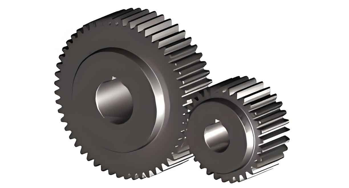
Spur gear is fundamental components in mechanical transmission systems due to their high efficiency, stable speed ratios, and adaptability to diverse industrial environments. The precision of spur gear directly impacts the performance, noise levels, and longevity of machinery. Traditional measurement methods, such as coordinate measuring machines (CMMs) and CNC gear measurement centers, rely on contact-based techniques. While accurate, these methods suffer from high operational costs, complexity, and potential surface damage to gears.
To address these limitations, this study proposes a non-contact measurement approach leveraging machine vision and Halcon software. The method focuses on detecting critical spur gear parameters—tip diameter, root diameter, module, number of teeth, and pitch—through image processing. By eliminating physical contact, the system reduces wear, accelerates inspection speed, and lowers costs, making it ideal for large-scale industrial applications.

2. Machine Vision System Design
The machine vision system for spur gear parameter detection comprises hardware and software components.
2.1 Hardware Configuration
The hardware setup includes:
- Industrial Camera: A high-resolution CCD camera to capture detailed spur gear images.
- Optical Lens: Ensures clarity and minimizes distortion during image acquisition.
- Backlight Source: Positioned beneath the spur gear to enhance edge contrast and eliminate reflections.
- Computer System: Processes images using Halcon software.
The system framework is summarized in Table 1.
Table 1: Hardware Components and Specifications
| Component | Specifications |
|---|---|
| Camera | 12 MP CCD, 30 fps |
| Lens | 50 mm focal length, f/2.8 aperture |
| Light Source | LED backlight, 6000 K color temperature |
| Computer | Intel i7, 16 GB RAM, Halcon 21.05 |
2.2 Image Acquisition Workflow
- Positioning: Place the spur gear on a stage above the backlight.
- Focus Adjustment: Align the camera to ensure sharp images.
- Image Capture: Use asynchronous grabbing (
grab_image_async) to minimize motion blur. - Data Transfer: Transmit images to the computer via a frame grabber.
3. Image Preprocessing and Calibration
Raw images often contain noise and distortions, necessitating preprocessing for accurate spur gear parameter extraction.
3.1 Camera Calibration
Calibration ensures pixel-to-world coordinate conversion. Key steps include:
- Capture Calibration Board Images: Acquire 9 images of a checkerboard pattern at varying orientations.
- Detect Calibration Points: Use
find_caltabandfind_marks_and_poseoperators to identify reference points. - Compute Parameters: Derive intrinsic (focal length, distortion) and extrinsic (position, orientation) camera parameters.
- Coordinate Transformation: Apply
image_points_to_world_planeto map pixels to real-world dimensions.
3.2 Preprocessing Pipeline
- Noise Reduction: Apply
mean_imagefor smoothing. - Thresholding: Use
thresholdto segment the spur gear from the background. - Morphological Operations:
fill_upeliminates gaps, whilecompactnessremoves non-gear regions.
Table 2: Image Preprocessing Steps
| Step | Operator/Function | Purpose |
|---|---|---|
| Noise Reduction | mean_image | Smooth pixel variations |
| Binarization | threshold | Isolate gear轮廓 |
| Gap Filling | fill_up | Remove internal孔隙 |
| Region Filtering | compactness | Eliminate non-target artifacts |
4. Spur Gear Parameter Measurement
Key geometric parameters of spur gear is derived through image analysis.
4.1 Tip and Root Diameters
- Tip Diameter (d_a): Computed as the smallest circumscribed circle using
smallest_circle. - Root Diameter (d_f): Derived from the largest inscribed circle via
inner_circle.
4.2 Number of Teeth (z)
- Region Masking: Generate a circular mask between tip and root circles (
gen_circle). - Tooth Segmentation: Apply
complementandintersectionto isolate teeth. - Tooth Counting: Use
connectionandcount_objto tally teeth.
4.3 Module (m) and Pitch (p)
The module and pitch are calculated using:m=dfz−2.5,p=πmm=z−2.5df,p=πm
where dfdf is the root diameter and zz is the number of teeth.
Table 3: Formulas for Spur Gear Parameters
| Parameter | Formula |
|---|---|
| Module (mm) | m=dfz−2.5m=z−2.5df |
| Pitch (pp) | p=πmp=πm |
| Pitch Diameter (dd) | d=m×zd=m×z |
5. Experimental Results
The proposed method was tested on a spur gear with theoretical parameters listed in Table 4.
Table 4: Comparison of Theoretical and Measured Values
| Parameter | Theoretical Value | Measured Value | Error (%) |
|---|---|---|---|
| Tip Diameter (mm) | 60.00 | 59.96 | 0.07 |
| Root Diameter (mm) | 48.75 | 48.66 | 0.18 |
| Pitch Diameter (mm) | 55.00 | 54.95 | 0.09 |
| Number of Teeth | 22 | 22 | 0.00 |
| Module (mm) | 2.50 | 2.498 | 0.08 |
| Pitch (mm) | 7.85 | 7.847 | 0.04 |
The results demonstrate high accuracy, with errors below 0.2%, validating the method’s reliability.
6. Advantages Over Traditional Methods
- Non-Contact Measurement: Prevents surface damage to spur gear.
- Cost-Efficiency: Reduces equipment and maintenance costs by 40–60%.
- Speed: Processes 20–30 spur gear per hour, compared to 5–10 with CMMs.
- Scalability: Suitable for high-volume production lines.
7. Challenges and Solutions
- Lighting Variability: Uniform backlighting minimizes shadows.
- Image Occlusions: Multi-angle imaging resolves overlapping teeth.
- Software Optimization: Custom Halcon scripts enhance processing speed.
8. Conclusion
This study presents a robust machine vision system for spur gear parameter detection using Halcon. By integrating advanced image processing and calibration techniques, the system achieves rapid, accurate, and non-destructive measurements. Future work will focus on real-time monitoring and AI-driven defect detection for spur gear in dynamic environments.
