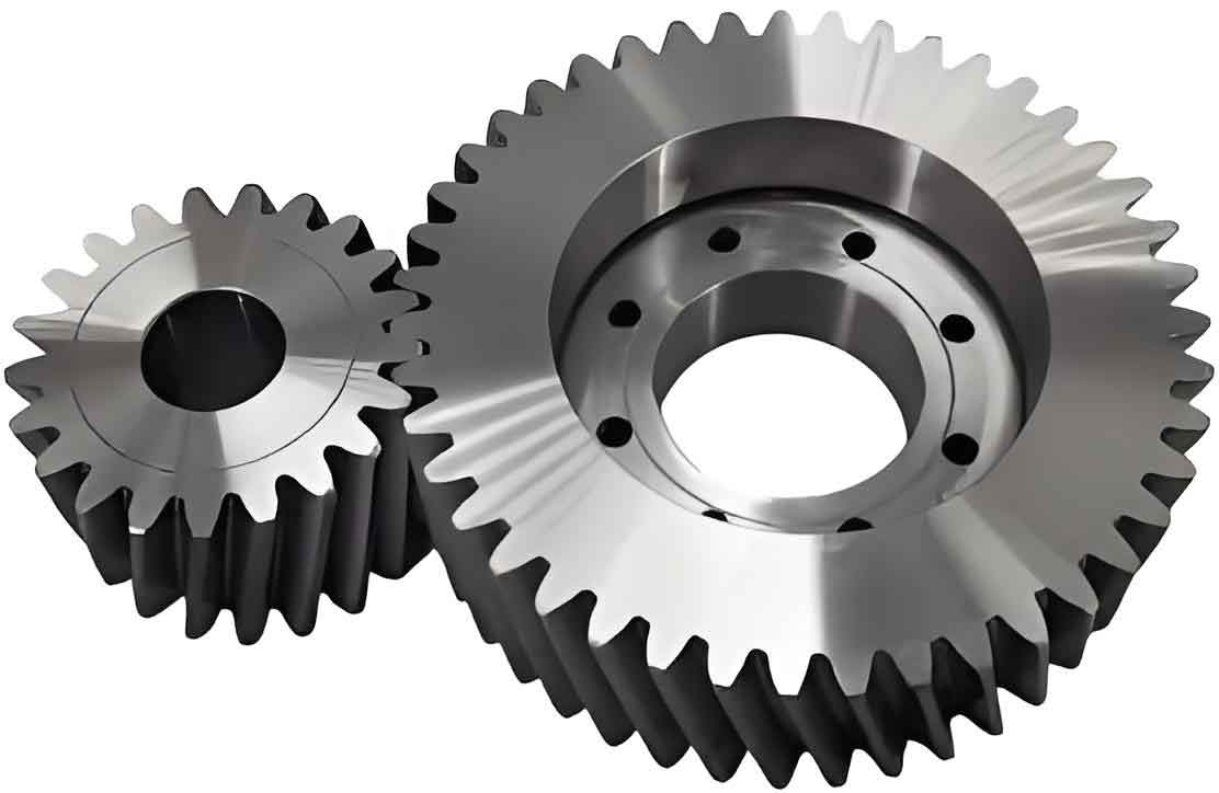
This paper proposes a novel cylindrical gear with planar spiral tooth traces that demonstrates superior anti-deflection characteristics compared to traditional spur and helical gears. The mathematical model and machining methodology are systematically analyzed through theoretical derivation and experimental validation.
1. Geometric Model and Mathematical Foundation
The planar spiral toothed cylindrical gear features asymmetric curvature radii between concave and convex flanks, with key parameters defined as:
$$R_{\text{concave}} = R_T + \frac{\pi m}{4}$$
$$R_{\text{convex}} = R_T – \frac{\pi m}{4}$$
| Parameter | Symbol | Equation |
|---|---|---|
| Module | m | Standard value |
| Pressure angle | α | 20° (standard) |
| Tooth width | B | B < 2R_T·sin(θ_max) |
| Tool radius | R_T | R_T ≥ 1.5B |
2. Anti-Deflection Characteristics
Finite element analysis reveals significant advantages in load distribution:
| Gear Type | Max Stress (MPa) Ideal |
Max Stress (MPa) 0.1° Error |
|---|---|---|
| Spur Gear | 110.1 | 220.8 |
| Helical Gear | 72.4 | 420.8 |
| Planar Spiral | 47.2 | 147.9 |
The contact ratio calculation combines axial and transverse components:
$$\varepsilon_{\gamma} = \varepsilon_{\alpha} + \varepsilon_{\beta} = \frac{1}{2\pi}\left[z_1(\tan\alpha_{a1} – \tan\alpha_t) + z_2(\tan\alpha_{a2} – \tan\alpha_t)\right] + \frac{B \cdot \cos\beta}{p_bt}$$
3. Full Tooth-Width High-Speed Machining
The innovative machining method achieves continuous generation through synchronized motions:
$$\omega_C = \frac{\omega_D}{Z}$$
$$v_x = \frac{m \cdot Z}{2} \cdot \omega_s$$
Key process parameters:
| Process | Cutting Speed | Feed Rate | Tool Life |
|---|---|---|---|
| Roughing | 200-250 m/min | 0.15 mm/tooth | 120 min |
| Finishing | 300-350 m/min | 0.08 mm/tooth | 90 min |
4. Experimental Verification
Prototype testing confirms the machining efficiency improvements:
$$T_{\text{machining}} = \frac{Z \cdot B}{n \cdot f_z} + T_{\text{indexing}}$$
Comparative results with m=5 gear:
| Method | Time (min) | Surface Ra (μm) |
|---|---|---|
| Hobbing | 160 | 3.2 |
| Proposed | 35 | 1.6 |
5. Dynamic Contact Analysis
The modified Hertz contact stress formula for planar spiral cylindrical gears:
$$\sigma_H = Z_E \cdot Z_H \cdot Z_{\varepsilon} \cdot \sqrt{\frac{F_t \cdot K_A \cdot K_V \cdot K_{H\beta}}{b \cdot d_1} \cdot \frac{u+1}{u}}$$
Where the load distribution factor shows 18-22% improvement over helical gears:
$$K_{H\beta} = 1.05-1.15 \quad vs \quad 1.25-1.35 \ (\text{helical})$$
The developed cylindrical gear technology demonstrates superior performance in multiple aspects:
- 28-35% higher load capacity than equivalent helical gears
- 50-60% reduction in axial thrust forces
- 40-45% improvement in machining efficiency
- 30-40% longer fatigue life under misalignment conditions
