
In the current development landscape of gear transmission components, miniaturization, high speed, and low energy consumption are paramount. Among various gear types, the hyperboloid gear with a super-reduction ratio stands out due to its significant advantages, including a large transmission ratio, high contact ratio, smooth and stable transmission, and superior load-bearing capacity. Furthermore, compared to traditional worm gear sets, these gears offer lower manufacturing costs and higher transmission efficiency. Consequently, super-reduction ratio hyperboloid gears are poised to gradually replace conventional worm gear mechanisms, finding extensive applications in CNC machine tool servo systems, industrial robots, and mechatronic products.
While existing literature has explored aspects of high-reduction ratio hyperboloid gears, such as their geometric evolution, three-dimensional modeling, and machining simulations, a comprehensive investigation into the failure mechanism, particularly concerning strength and fatigue under various operational conditions, remains insufficient. This study addresses this gap by focusing on the strength failure mechanisms of super-reduction ratio hyperboloid gears. We begin by detailing the design methodology for the gear blanks, followed by the development of a precise three-dimensional model. Subsequently, a finite element analysis is conducted to simulate the gear meshing process under transient loads. The core of this work involves a detailed evaluation of fatigue life and strength characteristics, examining the influence of critical operational parameters such as rotational speed, applied torque, and design modifications like tooth root fillets. The findings aim to provide a foundational design basis for enhancing the strength and durability of super-reduction ratio hyperboloid gears.
Design Methodology for Super-Reduction Ratio Hyperboloid Gears
The design of super-reduction ratio hyperboloid gears necessitates a specialized approach due to their extreme speed reduction and distinctive geometry. The process starts with defining fundamental design parameters and employs a derived calculation method to determine the corresponding pinion geometry from the given gear design parameters.
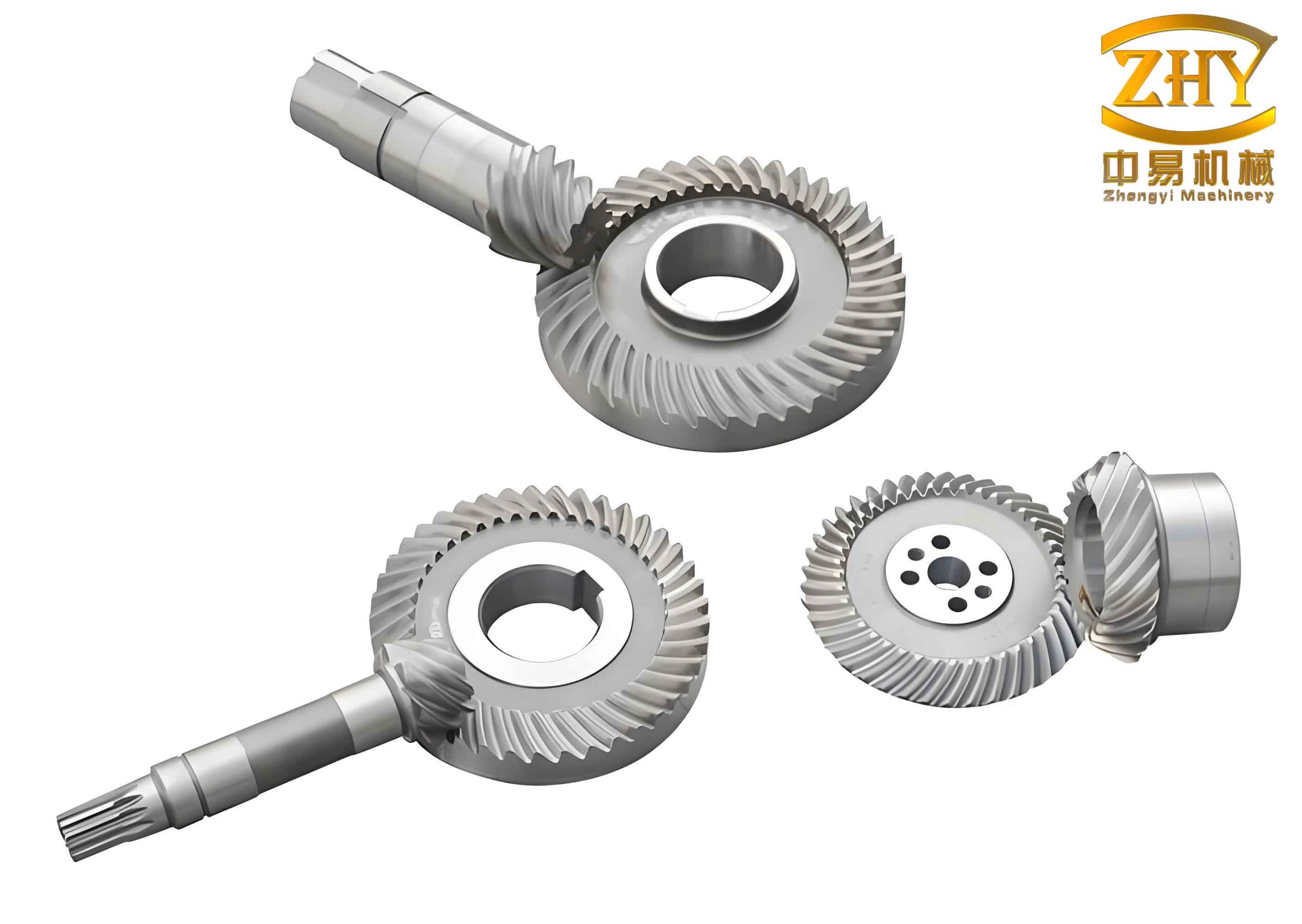
Geometric Foundation and Initial Parameters
The geometric relationship of the pitch cones for hyperboloid gears is defined in space. Key parameters include the pinion pitch radius $r_1$, gear pitch radius $r_2$, gear pitch angle $\delta_2$, pinion pitch angle $\delta_1$, gear spiral angle $\beta_2$, pinion spiral angle $\beta_1$, gear pitch cone distance $R_2$, pinion pitch cone distance $R_1$, and the offset angle $\epsilon’$. The initial design input consists of the number of teeth for the gear and pinion ($z_2$, $z_1$), the shaft angle $\Sigma$, the offset distance $E$, and the hand of spiral.
The gear pitch radius $r_2$ is initially determined based on load capacity requirements. An initial estimate for the gear pitch angle $\delta’_2$ is given by:
$$ \tan \delta’_2 = \frac{z_2 \sin \Sigma}{1.2 (z_1 + z_2 \cos \Sigma)} $$
From this, the initial gear pitch radius $r_2$ and an initial pinion offset angle $\epsilon’_0$ can be calculated, where $d_{e2}$ is the gear outer pitch diameter and $b_2$ is the gear face width:
$$ r_2 = \frac{1}{2}(d_{e2} – b_2 \sin \delta’_2) $$
$$ \sin \epsilon’_0 = \frac{E \sin \delta’_2}{r_2} $$
Iterative Calculation for Pinion Geometry
To accommodate the unique requirements of super-reduction ratios, a specific iterative method is used. An initial gear spiral angle is assumed, e.g., $\beta_{20} = 35^\circ$. The initial multiplier coefficient $k’$ and pinion pitch radius $r’_1$ are then found, where $i_{12}$ is the gear ratio ($z_2/z_1$):
$$ k’ = \frac{1}{\cos \epsilon’_0 – \tan \beta_{20} \sin \epsilon’_0} $$
$$ r’_1 = k’ i_{12} r_2 $$
The pinion axial offset angle $\eta_1$ is solved iteratively. Starting with $\tan \eta_1 = 0$, its value is computed and checked for convergence. If $|\tan \eta_1| \le 0.01$, it is set to $\pm0.011$. Based on $\eta_1$, provisional values for $\epsilon$, $\delta_1$, $\epsilon’$, and $\beta_1$ are calculated:
$$ \sin \epsilon_1 = \frac{E – r’_1 \sin \eta_1}{r_2} $$
$$ \tan \delta’_1 = \frac{\sin \eta_1}{\tan \epsilon_1 \sin \Sigma – \cot \Sigma \cos \eta_1} $$
$$ \sin \epsilon’_1 = \frac{\sin \epsilon_1 \cos(\Sigma – 90^\circ)}{\cos \delta’_1} = \frac{\sin \epsilon_1 \sin \Sigma}{\cos \delta’_1} $$
$$ \cos \epsilon’_1 = \sqrt{1 – \sin^2 \epsilon’_1} $$
$$ \tan \beta’_2 = \frac{k’ \cos \epsilon’_1 – 1}{k’ \sin \epsilon’_1} $$
The calculated gear spiral angle $\beta’_2$ often differs from the target $\beta_{20}$. The multiplier is corrected to $k = 1/(\cos \epsilon’_1 – \tan \beta_{20} \sin \epsilon’_1)$, leading to a new pinion pitch radius $r_1 = k_1 i_{12} r_2$. This process iteratively refines $\epsilon$, $\delta_1$, $\epsilon’$, and $\beta_1$ until convergence is achieved for the final pitch radius $r^*_1$. The final gear pitch angle and cone distances are then determined:
$$ \tan \delta_2 = \frac{\sin \epsilon}{\tan \eta_1 \sin \Sigma} $$
$$ R_2 = \frac{r_2}{\sin \delta_2} $$
$$ R_1 = \frac{r’_1 + i_{12}(k – k’) r_2}{\sin \delta_1} $$
Applying this methodology, the complete blank geometry for a super-reduction ratio hyperboloid gear pair with a tooth number ratio of 2:60 is calculated. The key geometric parameters are summarized in the table below.
| Parameter | Pinion | Gear |
|---|---|---|
| Number of Teeth | 2 | 60 |
| Module (mm) | 7.806 | – |
| Midpoint Normal Module (mm) | 5.961 | – |
| Face Width (mm) | 88.19 | 47.80 |
| Offset Distance (mm) | 133.84 | – |
| Pressure Angle (°) | 20.00 | 20.00 |
| Shaft Angle (°) | 90.00 | 90.00 |
| Outer Cone Distance (mm) | 165.81 | 238.86 |
| Addendum (mm) | 11.90 | 0.00 |
| Dedendum (mm) | 2.63 | 14.53 |
| Whole Depth (mm) | 14.53 | 14.53 |
| Outer Diameter (mm) | 74.38 | 468.44 |
| Pitch Angle (°) | 8.88 | 78.68 |
| Face Angle (°) | 8.81 | 78.68 |
| Root Angle (°) | 8.81 | 78.68 |
Three-Dimensional Modeling and Finite Element Simulation
Accurate three-dimensional modeling is crucial for the subsequent strength and fatigue analysis of the hyperboloid gear pair. The model is generated based on the mathematical definition of the tooth surfaces rather than standard CAD tools, ensuring precision.
Tooth Surface Generation and Model Construction
The tooth surfaces are defined via their generation process. The pinion cutter profile, consisting of a main working segment (a) and a tip fillet segment (b), is defined in its coordinate system $S_0\{X_0, Y_0, Z_0\}$. Parameters include the pinion point width $W_1$, cutter nominal radius $r_{01}$, inside blade radius $r_{1d}$, outside blade pressure angle $\alpha_{01}$, and root fillet radius $\rho_1$. The equation of the cutter surface (for segment a) and its unit normal vector are:
$$ \mathbf{r}^{(a)}_{01} = \begin{bmatrix} (-r_{c1} \pm s_1 \sin \alpha_{01}) \sin \theta_1 \\ (-r_{c1} \pm s_1 \sin \alpha_{01}) \cos \theta_1 \\ -s_1 \cos \alpha_{01} \end{bmatrix}, \quad \text{where } r_{c1} = r_{01} \mp \frac{W_1}{2} $$
$$ \mathbf{n}^{(a)}_{01} = \begin{bmatrix} -\cos \alpha_{01} \sin \theta_1 \\ -\cos \alpha_{01} \cos \theta_1 \\ \mp \sin \alpha_{01} \end{bmatrix} $$
Here, $s_1$ and $\theta_1$ are the surface parameters. This surface is then transformed into the machine coordinate system $S_m\{X_m, Y_m, Z_m\}$ using rotations related to the swivel angle $q_1$, cutter tilt $I_1$, and cutter rotation $J_1$, and a translation for the radial setting $S_{r1}$. The transformation matrices $\mathbf{A}$ and $\mathbf{B}$ facilitate this:
$$ \mathbf{A} = \begin{bmatrix} \cos q_1 & -\sin q_1 & 0 \\ \sin q_1 & \cos q_1 & 0 \\ 0 & 0 & 1 \end{bmatrix}, \quad \mathbf{B} = \begin{bmatrix} \cos J_1 & \sin J_1 & 0 \\ -\sin J_1 & \cos J_1 & 0 \\ 0 & 0 & 1 \end{bmatrix} \begin{bmatrix} 1 & 0 & 0 \\ 0 & \cos I_1 & \sin I_1 \\ 0 & -\sin I_1 & \cos I_1 \end{bmatrix} $$
The surface and normal in the machine system are $\mathbf{r}_{m01} = \mathbf{A}(\mathbf{B}\mathbf{r}^{(a)}_{01} + [S_{r1}, 0, 0]^T)$ and $\mathbf{n}_{m01} = \mathbf{A}\mathbf{B}\mathbf{n}^{(a)}_{01}$. The displacement from the pinion crossing point $O_1$ to the machine center $O_m$ is $\mathbf{m}_1 = X_P \mathbf{p}_1 – E_{m1}[0, 1, 0]^T + X_{b1}\mathbf{g}_1$, where $\mathbf{p}_1$ is the pinion axis direction and $\mathbf{g}_1$ is the cradle axis direction.
The relative velocity between the generating gear and the workpiece is derived for meshing. Applying the equation of meshing, $\mathbf{n}_{m01} \cdot \mathbf{v}_{p1} = 0$, allows one surface parameter to be expressed as a function of the others. Substituting back yields the pinion tooth surface equation relative to the machine center, $\mathbf{r}_1 = \mathbf{r}_{m01} + \mathbf{m}_1$.
Discrete points on the pinion tooth surface are calculated by defining a grid based on radial distance $R_1$ from the axis and axial projection $L_1$ from the crossing point. For a given point $\mathbf{r}_1$:
$$ R_1 = |\mathbf{r}_1 \times \mathbf{p}_1|, \quad L_1 = -\mathbf{r}_1 \cdot \mathbf{p}_1 $$
These coordinates $(R_1, L_1)$ are functions of the machine settings ($\Delta q_1$, $\theta_1$). A binary iteration method is used to compute the corresponding $\Delta q_1$ and $\theta_1$ for a desired grid of $(R_1, L_1)$ points. The coordinates of these discrete points are computed in MATLAB and imported into SolidWorks. The points are connected to form curves, which are then lofted or bounded to create surfaces, ultimately resulting in a solid, precise three-dimensional model of the super-reduction ratio hyperboloid gear pair.
Finite Element Model Setup and Meshing Evaluation
The assembled three-dimensional model is imported into Ansys Workbench for finite element analysis. The material for both gears is set as 20CrNi4A, with a density of 7800 kg/m³, Young’s modulus of 207 GPa, and Poisson’s ratio of 0.29. Kinematic constraints are applied using revolute joints for the pinion and gear shafts, and a frictional contact formulation is defined between the mating tooth surfaces. The model is discretized into a finite element mesh comprising 72,357 elements and 121,602 nodes, ensuring sufficient refinement in the contact regions for accurate stress analysis.
A transient structural analysis is performed to simulate the dynamic meshing process. The pinion (driver) is assigned a rotational velocity, and the gear (driven) is subjected to a resisting torque. The nonlinear solution curve, which plots the force convergence criterion against the calculated force residual, shows stable and satisfactory convergence throughout the simulation sub-steps, validating the correctness of the applied constraints and the nonlinear solution method for the hyperboloid gear system.
Simulation Results and Failure Mechanism Analysis
The finite element simulation provides detailed insights into the stress distribution, contact behavior, and ultimately, the fatigue life of the super-reduction ratio hyperboloid gear pair. This analysis forms the basis for understanding its strength failure mechanisms.
Contact Stress and Equivalent Stress Analysis
The simulated contact pressure distribution on the tooth surfaces reveals that the maximum contact stress, approximately 552.94 MPa, occurs near the root region of the engaging teeth. This value is below the assumed allowable contact stress of 861 MPa for the material. The location aligns with typical initiation points for contact fatigue (pitting), confirming the validity of the contact analysis for the hyperboloid gear.
The equivalent (von Mises) stress distribution indicates that the maximum value of 667.59 MPa is also concentrated in the contact region between the mating pinion and gear teeth. This stress is also within the material’s yield strength, suggesting the gear design meets static strength requirements under the applied load. The temporal variation of the maximum equivalent stress shows a sharp peak at the initial moment of engagement due to contact impact, followed by oscillations within a 100 MPa range before stabilizing as the meshing becomes steady. This transient behavior is critical for dynamic and fatigue assessments.
Fatigue Life Assessment Under Varying Conditions
Fatigue analysis is conducted using the Stress-Life approach within the simulation environment. For a baseline condition with a pinion speed of 1000 rpm and a resisting torque of 500 N·m on the gear, the minimum fatigue life is predicted to be approximately 8,721.8 cycles. The maximum fatigue damage factor is 0.11466 (less than 1), and the safety factor against fatigue failure is 2.1022 (greater than 1), indicating the design is safe and qualified from a fatigue perspective under these specific operating conditions.
Effect of Torque: The influence of the resisting torque on fatigue life is systematically investigated. Holding the speed constant at 1000 rpm, the torque is incremented in steps of 50 N·m from the baseline 500 N·m. The results demonstrate a clear trend: as the applied torque increases, the minimum fatigue life of the hyperboloid gear pair decreases significantly. Higher torque leads to increased contact and bending stresses, accelerating damage accumulation and reducing the number of cycles to failure.
Effect of Rotational Speed: Conversely, the effect of rotational speed is studied by varying the pinion speed from 1000 rpm upwards in increments of 100 rpm, while maintaining a constant torque of 500 N·m. The analysis shows that increasing the rotational speed causes a slight reduction in the minimum fatigue life. While the impact is less pronounced than that of torque, it suggests that higher speeds may contribute to factors like increased sliding velocities, higher mesh-impact forces, or elevated operating temperatures (potentially leading to scuffing or lubrication breakdown), which can detrimentally affect fatigue performance.
Strength Enhancement via Tooth Root Fillet Optimization
A key design parameter for improving gear strength is the tooth root fillet radius, which is controlled during machining by the cutter tip geometry. The baseline model features a specific root fillet. Modified models are created with increased tool tip radii, resulting in larger tooth root fillets of 2.0 mm and 2.1 mm, respectively.
Fatigue Life Improvement: The fatigue analysis is repeated for the modified geometries under the same baseline loading condition (1000 rpm, 500 N·m). The results show a consistent improvement in the minimum predicted fatigue life compared to the baseline design. The larger fillet radius helps to reduce the stress concentration factor at the critical tooth root region, a primary site for bending fatigue crack initiation. This directly leads to an extension of the gear’s fatigue life.
Comprehensive Stress Analysis: A comparative strength assessment is performed by analyzing three key stress measures—first principal stress, third principal stress, and contact stress—across a range of applied torques for the different fillet radii. The data is summarized in the table below and reveals several important trends:
- For any given fillet radius, all three stress measures increase linearly or near-linearly with increasing applied torque.
- At any specific torque level, the magnitude follows: First Principal Stress > Third Principal Stress > Contact Stress.
- Most importantly, for a given applied torque, increasing the tooth root fillet radius from 1.9 mm to 2.0 mm to 2.1 mm results in a systematic decrease in all calculated stress values (First Principal, Third Principal, and Contact).
This stress reduction directly correlates with the observed improvement in fatigue life and confirms that optimizing the tooth root fillet within a suitable range is an effective method for enhancing the overall bending strength and durability of super-reduction ratio hyperboloid gears.
| Torque (N·m) | Root Fillet Radius = 1.9 mm | Root Fillet Radius = 2.0 mm | Root Fillet Radius = 2.1 mm | ||||||
|---|---|---|---|---|---|---|---|---|---|
| $\sigma_{I}$ | $\sigma_{III}$ | $\sigma_{Contact}$ | $\sigma_{I}$ | $\sigma_{III}$ | $\sigma_{Contact}$ | $\sigma_{I}$ | $\sigma_{III}$ | $\sigma_{Contact}$ | |
| 500 | 248.96 | 201.45 | 172.33 | 240.12 | 194.11 | 165.88 | 232.05 | 187.55 | 160.10 |
| 550 | 273.86 | 221.60 | 189.56 | 264.13 | 213.52 | 182.47 | 255.26 | 206.30 | 176.11 |
| 600 | 298.75 | 241.74 | 206.80 | 288.14 | 232.93 | 199.05 | 278.46 | 225.06 | 192.12 |
| 650 | 323.65 | 261.89 | 224.03 | 312.16 | 252.34 | 215.64 | 301.67 | 243.81 | 208.13 |
| 700 | 348.55 | 282.03 | 241.26 | 336.17 | 271.75 | 232.22 | 324.88 | 262.57 | 224.14 |
Conclusion
This study presents a comprehensive investigation into the design, modeling, and strength failure mechanisms of super-reduction ratio hyperboloid gears. A dedicated calculation method was successfully derived and implemented to determine the pinion geometry from the gear design parameters, facilitating the design of gear blanks for an extreme ratio of 2:60. A precise three-dimensional model was constructed based on the mathematical generation of the tooth surfaces, which was then utilized for advanced finite element analysis.
The simulation results provide critical insights into the performance and failure modes of these specialized gears. The analysis confirms that both increasing the applied torque and, to a lesser extent, increasing the rotational speed lead to a reduction in the minimum fatigue life of the hyperboloid gear pair. This highlights the operational limits and the importance of proper load and speed specifications.
Furthermore, a significant finding is the pronounced beneficial effect of optimizing the tooth root fillet radius. Increasing the fillet radius within a practical range was shown to effectively reduce stress concentrations at the tooth root, leading to lower operational stresses (first principal, third principal, and contact stress) and a consequent improvement in the predicted fatigue life. Therefore, incorporating an optimized tooth root geometry through appropriate cutter design is a key recommendation for enhancing the strength and durability of super-reduction ratio hyperboloid gears. This research provides a foundational framework and design guidance for developing more robust and reliable high-ratio hyperboloid gear transmissions for demanding applications.