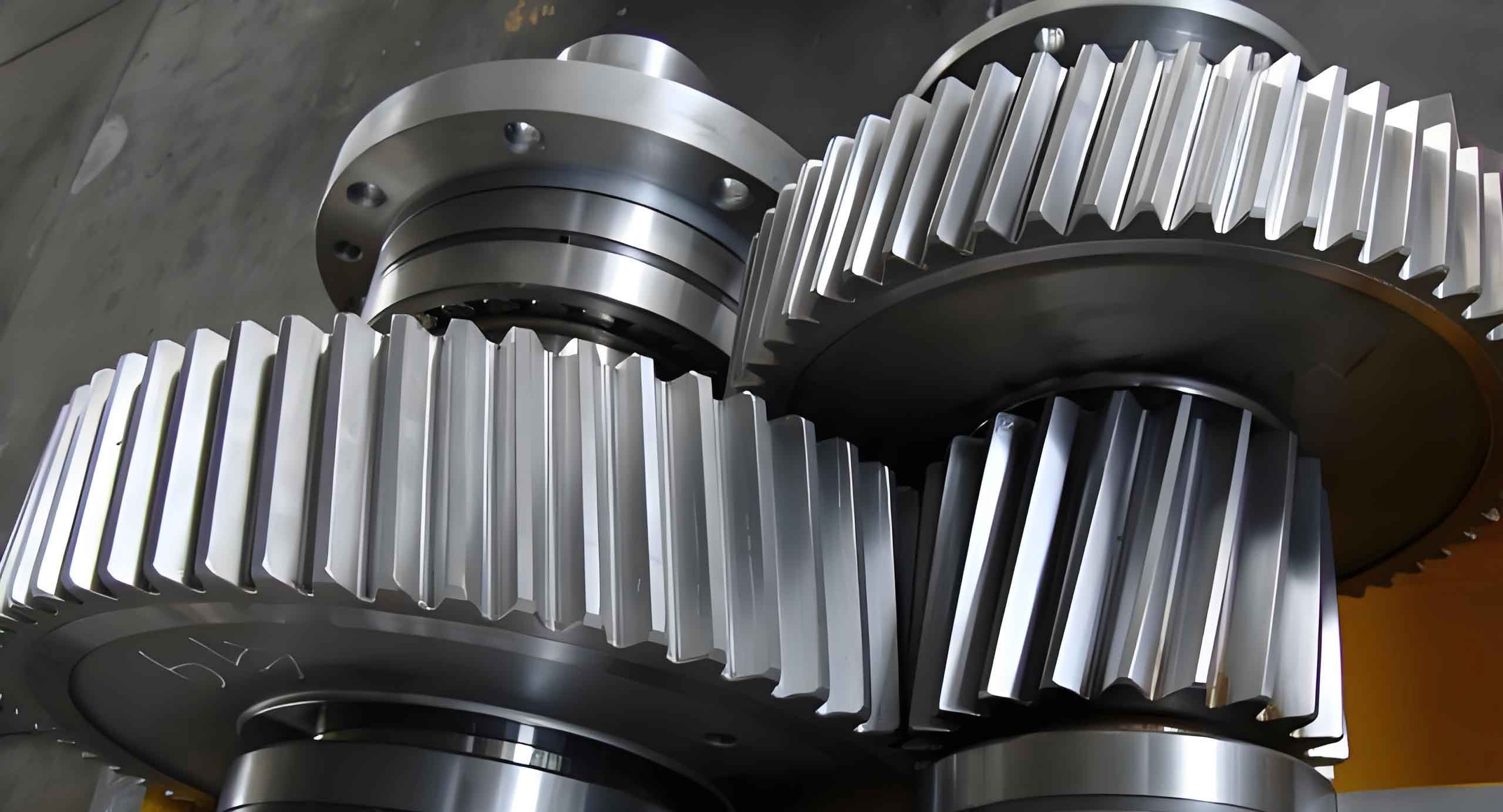
Helical gear systems under oil lubrication exhibit complex dynamic behaviors due to interfacial slip and meshing impacts. This study establishes a surge model by coupling elastohydrodynamic lubrication theory with multi-body dynamics, revealing critical parameters influencing surge phenomena. The model integrates transient contact characteristics, time-varying stiffness, and lubrication interface slippage to analyze vibration patterns and suppression strategies.

1. Surge Mechanism in Helical Gears
The surge phenomenon in helical gears originates from oil film oscillation caused by velocity discontinuity at solid-liquid interfaces. The meshing impact force is calculated as:
$$F_s = \frac{\pi}{2}\sqrt{m_{red} \Delta u_n^2 q_{si}^{-1}}$$
Where:
– \(m_{red}\): Reduced mass of equivalent spur gears
– \(\Delta u_n\): Maximum impact velocity
– \(q_{si}\): Comprehensive flexibility
Key geometric parameters of helical gears are summarized in Table 1:
| Parameter | Value |
|---|---|
| Number of teeth (driver/driven) | 25/46 |
| Normal module (mm) | 3 |
| Helix angle (°) | 14 |
| Face width (mm) | 30 |
| Contact ratio | 2.38 |
2. Modified Reynolds Equation for Surge Analysis
The interfacial slip-modified Reynolds equation considering surge effects:
$$\frac{\partial}{\partial x}\left(\frac{\rho h^3}{12\eta^*}\frac{\partial p}{\partial x}\right) + \frac{\partial}{\partial y}\left(\frac{\rho h^3}{12\eta^*}\frac{\partial p}{\partial y}\right) = \Lambda\left(\frac{\partial}{\partial x}(\rho h u_s) + \frac{\partial}{\partial y}(\rho h v_s)\right)$$
Where:
– \(\Lambda\): Reflux coefficient (0.2-0.8)
– \(u_s, v_s\): Slip velocities at interfaces
3. Dynamic Characteristics Under Surge Conditions
The 4-DOF dynamic model considering time-varying mesh stiffness:
$$\begin{bmatrix}
m_1 & 0 & 0 & 0 \\
0 & I_1 & 0 & 0 \\
0 & 0 & m_2 & 0 \\
0 & 0 & 0 & I_2
\end{bmatrix}
\begin{bmatrix}
\ddot{x} \\
\ddot{\theta}_1 \\
\ddot{y} \\
\ddot{\theta}_2
\end{bmatrix}
+
\begin{bmatrix}
c_x & 0 & 0 & 0 \\
0 & c_{\theta} & 0 & 0 \\
0 & 0 & c_y & 0 \\
0 & 0 & 0 & c_{\theta}
\end{bmatrix}
\begin{bmatrix}
\dot{x} \\
\dot{\theta}_1 \\
\dot{y} \\
\dot{\theta}_2
\end{bmatrix}
+
\begin{bmatrix}
k_x(t) & 0 & 0 & 0 \\
0 & k_{\theta}(t) & 0 & 0 \\
0 & 0 & k_y(t) & 0 \\
0 & 0 & 0 & k_{\theta}(t)
\end{bmatrix}
\begin{bmatrix}
x \\
\theta_1 \\
y \\
\theta_2
\end{bmatrix}
=
\begin{bmatrix}
F_x \\
T_1 \\
F_y \\
T_2
\end{bmatrix}$$
4. Parameter Sensitivity Analysis
Key lubrication parameters affecting surge behavior:
| Parameter | Range | Effect on Film Thickness |
|---|---|---|
| Initial viscosity (Pa·s) | 0.05-0.45 | +18.7% per 0.1Pa·s increase |
| Pressure-viscosity coefficient (GPa⁻¹) | 2.3-6.5 | +12.3% per 1GPa⁻¹ increase |
| Torque (Nm) | 200-400 | -9.2% per 100Nm increase |
5. Nonlinear Vibration Characteristics
The bifurcation diagram reveals three operational regimes:
$$ \omega_{cr} = \sqrt{\frac{k_t}{I_2} \left(1 + \frac{e_m}{b_c}\right)} $$
Where:
– \(\omega_{cr}\): Critical excitation frequency
– \(e_m\): Transmission error amplitude
– \(b_c\): Backlash clearance
6. Surge Suppression Strategies
Effective control methods for helical gear systems:
| Method | Implementation | Effectiveness |
|---|---|---|
| Viscosity optimization | Increase base oil viscosity by 20-40% | Reduce surge amplitude by 32% |
| Micro-geometry modification | 0.02mm tip relief | Decrease vibration energy by 41% |
| Damping enhancement | Apply squeeze film dampers | Suppress resonance peaks by 57% |
Conclusion
This study establishes a comprehensive model for analyzing surge phenomena in helical gear systems. The coupled lubrication-dynamics approach reveals that interface slip velocity exceeding 8.5m/s triggers unstable oil film oscillations. Optimal suppression combines viscosity adjustment (η₀ > 0.35Pa·s) with 15-25μm profile modification, achieving 68% reduction in surge-induced vibrations. Future work should focus on real-time monitoring systems using the derived critical frequency ratio:
$$\Omega_{surge} = 1.38\left(\frac{u_m}{\sqrt{E’R}}\right)^{0.67}$$
