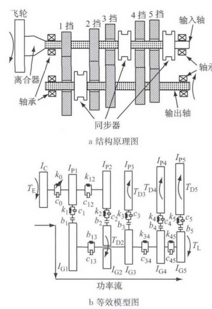
Automobile transmission includes many pairs of helical gear pairs, multiple bearings and synchronizer assemblies, etc. when considering the spatial meshing characteristics of helical gear pairs, transmission shaft stiffness (torsional stiffness and bending stiffness), nonlinear dynamic characteristics of bearings, etc., more complex transmission gear knock models are established, and the models used for research are classified, It includes system parameter model based on lumped mass and system parameter model based on continuous distributed parameter.
This simplified transmission modeling method has been widely used by using the lumped mass system parameter model, which only considers the vibration in the rotation direction of the gear, and does not consider the axial and radial vibration of the gear. For example, Wang et al. [14] had earlier refined the connection between the various components in the transmission, only considering the torsional direction movement of the components, According to the actual position on the transmission shaft, the internal gear of the transmission is equivalent to a single moment of inertia, and the transmission shaft between the gears is equivalent to a single torsional stiffness and torsional damping, as shown in Figure 3B. For the variable description in the figure, please refer to literature. Considering the nonlinear dynamic characteristics of the clutch in the model, the whole transmission gear system is divided into the main torsional vibration and the secondary torsional vibration, The impact of meshing lubrication and friction on the transmission force is not considered in the meshing gear pairs. The knock strength of each non load bearing gear pair when the transmission is in gear 1 is analyzed by numerical simulation, and the knock strength of the gear system when the traditional clutch and dual mass flywheel (DMF) are compared, The results show that DMF can restrain the knock phenomenon of transmission gear. For a three-axis six speed manual transmission, de la Cruz m et al. Did not refine the connection between the components in the transmission, but considered the different lubrication conditions of the gear tooth mesh surfaces of the load-bearing gear and the non load-bearing gear in detail, and put forward the knock indexes including different lubrication state indexes, In the test, the vibration acceleration signal of the box surface near the transmission output shaft is collected, and the frequency spectrum results of the simulation data are in good agreement with the peak frequency in the frequency domain results of the test signal, which provides a theoretical basis for the transmission modeling considering the influence of lubrication and friction. However, the transmission gear knock model established by Wang and de la Cruz m et al, Bearing gear pair and non bearing gear pair do not consider the influence of time-varying meshing stiffness and static transmission error of gear, which will become an important research direction based on lumped mass system parameter model in the future.

By using the continuous distributed parameter system model, the finite element method is used to solve the problem, and the subspace iterative method and the determinant search method are used to solve the eigenvalue of the system, while the step-by-step iterative method is used to calculate the dynamic response of the system, At this time, the change of meshing stiffness of helical gear pair caused by the change of space displacement should be fully considered, and the gear pair model based on space displacement should be established [16]; the force of transmission shaft is no longer a single torsion direction force, but a space beam subject to bending torsion tension, at this time, the continuous distributed mass of transmission shaft is discretized into a finite space beam element [17]; the bearing is also subject to space force, It is necessary to establish a nonlinear stiffness bearing model based on contact parameters [18]; for other rotating parts on the transmission shaft, the rotational inertia force should be equivalent to the joint force of the beam element of the transmission shaft. At present, there are few research results based on the continuous analysis parameter system at home and abroad, which will become an important research direction on the problem of transmission gear knocking.
In addition, in addition to the above-mentioned numerical simulation analysis using physical model and mathematical model, there are a variety of mature commercial software available for the analysis of the knock model of automobile transmission gear. Guo Lei et al. [19] used the commercial software Tycon, adopted the multi-body dynamics method to establish the five gear transmission model, and analyzed the time-domain and frequency-domain characteristics of the dynamic meshing force of the neutral gear; Chen et al. Established a model of a double clutch automatic transmission by using valdyn software, analyzed and compared the knock strength (knock force and knock power) of the non bearing gear pair of the transmission when three different clutches were used, providing theoretical basis for the selection of appropriate clutches for the real vehicle.
