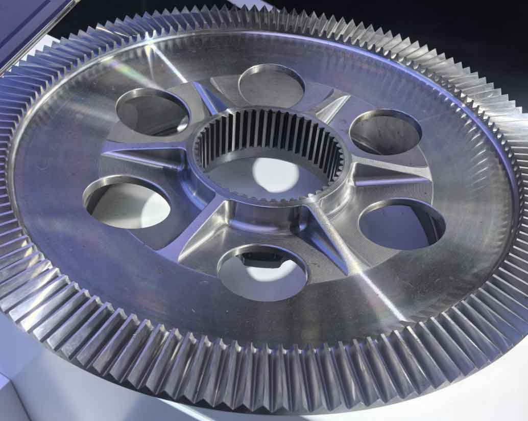
With rapid economic development, heavy machinery like mining equipment, construction machinery, and offshore engineering systems are extensively utilized across energy, marine, transportation, and metallurgy sectors. Gear rack drives, known for structural simplicity and direct power transmission, are widely adopted in these applications. Historically, core technologies for such equipment were monopolized by foreign entities, but domestic advancements have enabled localization. As critical transmission components, the reliability of gear racks profoundly impacts overall performance.
Tooth fracture represents the most severe failure mode for heavy-duty gears, potentially causing catastrophic losses. Thus, enhancing bending strength is paramount. Heavy-duty gear racks typically feature large modules and pinions with minimal teeth. For instance, climbing gears in jack-up drilling platforms commonly use 7 teeth with modules of 80–100 mm, while large excavator rack-and-pinion systems employ 14 teeth with modules of 40–50 mm. Existing gear technology lacks standardized design protocols or mature computational software for these large-module systems. Current practices rely on iterative finite element analysis (FEA) for tooth root stress validation, leading to cumbersome redesign loops. This study addresses these gaps through specialized tooth profile optimization and efficient stress-calculation methodologies.
Tooth Profile Design Methodology
Large-module gears evade conventional hobbing or shaping processes. Pinions require custom milling strategies, while racks necessitate CNC machining or casting. Early designs in mining excavators used three-segment circular arcs approximating involutes, but these caused excessive vibration, wear, and fractures due to transmission errors. Optimized gear technology prioritizes parametric refinement.

Tip Thickness (Sa): For fatigue-loaded open gears, Sa ≥ 0.4m prevents rapid wear. Static-load applications (e.g., drilling platforms) tolerate Sa ≥ 0.15m. Empirical data from XP2300/XP2800 excavators (Sa ≈ 0.41m–0.42m) and NOV platforms (Sa ≈ 0.14m–0.15m) validate this. Calculated as:
$$S_a = d_a \left( \frac{\pi}{2Z} + \text{inv } \alpha – \text{inv } \alpha_a \right),$$
$$\cos \alpha_a = \frac{d_b}{d_a},$$
where da = tip diameter, αa = tip pressure angle, and m = module.
Contact Ratio (ε): For fatigue-loaded gears, ε ≥ 1.2 minimizes impact loads. Static-load systems require ε ≥ 1.05 since high pressure angles (>25°) reduce tip thickness, risking plastic deformation. The contact ratio derives from:
$$\varepsilon = \frac{Z_1 (\tan \alpha_{a1} – \tan \alpha)}{2\pi} + \frac{2h’_{a2}}{\pi m \sin 2\alpha},$$
where h’a2 = effective rack addendum height.
Backlash: Accounting for manufacturing tolerances, thermal expansion, and mounting errors, backlash ranges between 0.12m–0.15m, achieved by thinning tooth thicknesses while maintaining robust rack roots.
Root Fillet Optimization: Single-root fillets reduce stress concentrations versus double fillets but risk meshing interference. Maximizing fillet radius (rρ) without compromising contact ratio or tip thickness is ideal. Pinion fillet radius is calculated as:
$$r_\rho = \frac{D_b}{2} \left[ \tan\left( \alpha_{ce} + \text{inv } \alpha_{ce} + \frac{\pi}{Z} – \frac{S_{\text{min}}}{D} – \text{inv } \alpha \right) – \tan \alpha_{ce} \right],$$
$$\alpha_{ce} = \arccos\left( \frac{D_b}{D_{ce}} \right),$$
where Dce ≈ Db + (2\text{–}3 \text{ mm}) defines the tangency point between fillet and involute curve.
Rack Profile Design: Effective rack height (ha2e) ensures lubrication and clearance:
$$h’_{a2} = r_a – r_{ce} \cos(\alpha – \alpha_{ce}),$$
$$h_{a2e} = h’_{a2} + X m,$$
$$h_{a2} = h_{f1} – C_m^*,$$
where Cm* = tip clearance (10–12 mm for open gears).
Tooth Root Bending Stress Calculation
Heavy-duty gear racks lack dedicated computational tools. While ISO’s 30° tangent method offers ±5% accuracy versus complex mapping functions, its adaptation enables rapid design validation. Critical considerations include:
Load Distribution Coefficient (Ka): Low manufacturing precision causes single-tooth engagement despite ε > 1.2. Ka determines load application points:
$$K_a = \frac{\varepsilon}{2} \left( 0.9 + \frac{0.4 C_r \Delta}{F_{t\text{eff}} \right),$$
where Cr = mean mesh stiffness, Δ = base pitch error, and Fteff = effective tangential load. Ka ≤ 1 indicates peak stress at the highest point of single-tooth contact (HPSTC); Ka ≥ 1 mandates tip-load assessment.
Root Stress Formulation: For low-precision gears (ISO > grade 11), tip-load conditions govern. Stress at the critical section follows:
$$\sigma_{F0} = \frac{F_n \cos \delta_a}{b m} Y_{Fa} Y_{Sa},$$
$$Y_{Fa} = \frac{6 (h_F / m) \cos \delta_a}{(S_F / m)^2 \csc \alpha},$$
$$Y_{Sa} = (1.2 + 0.13 L_a) q_s^{1/(1.21 + 2.3/L_a)},$$
where SF = critical section width and hF = load moment arm.
| Parameter | Gear | Rack |
|---|---|---|
| SF | $$2(r_f + r_\rho) \sin\frac{\pi}{Z} – 2r_\rho \cos 30^\circ$$ | $$\pi m – 2 r_\rho \cos 30^\circ – e$$ |
| hF | $$\frac{r_b}{\cos \delta_a} – (r_f + r_\rho) \cos\frac{\pi}{Z} + r_\rho \sin 30^\circ$$ | $$h – \frac{S_a}{2} \tan \alpha – r_\rho (1 – \sin 30^\circ)$$ |
Load Angle (δa): Varies by position:
$$\delta_a = \psi – \theta – \text{inv } \alpha,$$
$$\theta = \frac{1}{Z} \left( \frac{\pi}{2} + 2X \tan \alpha \right),$$
$$\psi = \sqrt{ \left( \frac{r_a}{r_b} \right)^2 – 1 }.$$
Case Study: Jack-Up Drilling Platform
A 300-ft platform climbing gear (module = 80 mm, teeth = 7, face width = 190 mm) under 2000 kN load demonstrates the methodology.
| Design Parameter | Value |
|---|---|
| Root Fillet Radius (rρ) | 35 mm |
| Tip Thickness (Sa) | 0.15m |
FEA validation modeled single-tooth engagement under meshing extremes. Comparative stresses:
| Component | Analytical (MPa) | FEA (MPa) | Error (%) |
|---|---|---|---|
| Pinion Root | 574 | 546 | 5.1 |
| Rack Root | 514 | 501 | 2.5 |
Sub-5.1% deviations confirm method reliability for static-loaded systems. Material yield limits remain the primary failure criterion.
Conclusions
1) Specialized tooth profiles balancing tip thickness, contact ratio, backlash, and fillet geometry enhance durability in heavy-duty gear technology.
2) Load distribution coefficients (Ka > 1) validate tip-load stress calculations for low-precision large-module gears.
3) The adapted 30° tangent method achieves <10% error versus FEA, enabling efficient design iteration without complex modeling.
This research advances gear technology for extreme-duty applications by integrating practical design rules with computationally efficient mechanics.
