
Abstract: This article focuses on the research of spiral bevel gear, an important component in automotive transmission systems. It explores the deformation and the influence of forging parameters on their performance. Through the use of Solidworks software and its Simulation module, digital and finite element models of spiral bevel gear is established. Orthogonal experimental methods are employed to determine the optimal forging parameters. The article analyzes the forging forming of the gear tooth surface under specific temperature and load conditions, presenting detailed experimental results and discussions on stress, displacement, and contact stress. The research findings have significant implications for improving the quality and production efficiency of spiral bevel gear.
1. Introduction
Spiral bevel gear play crucial role in automotive transmission systems due to their excellent load-bearing capacity, strong transmission performance, high overlap coefficient, and low transmission noise. They are widely used in automotive manufacturing and high-end machine tools. Traditional gear manufacturing methods such as cutting have limitations in terms of material flow organization and production efficiency. In contrast, precision forging techniques, especially warm forging, offer advantages like high processing precision, good material organization flow, and improved die life. This article aims to study the warm forging process of spiral bevel gear in detail.
1.1 Previous Research
Many scholars have conducted research on gear forging. Zhang Zaiping analyzed the warm forging forming of a shaft gear and improved the forging die structure. Cao Guoying studied the warm forging of an automotive transmission drive gear shaft, considering factors like initial billet temperature and friction. Huang Sitao used Deform – 3D technology for numerical simulation of straight cylindrical gear precision forging. These studies highlight the importance of warm forging in improving gear production efficiency and quality.
2. Establishment of Spiral Bevel Gear Model
2.1 Material Properties
The selected material for the automotive spiral bevel gear in this study is X38CrMoV5 – 3 alloy steel. Its properties are shown in Table 1.
| Elastic Modulus/(N/mm²) | Poisson’s Ratio | Thermal Expansion Coefficient | Tensile Strength/MPa | Yield Strength/MPa | Elongation/% | Hardness HRC |
|---|---|---|---|---|---|---|
| 215000 | 0.28 | 50 – 54 | 2000 | 1800 | 1.1×10⁻⁵ | 10 – 14 |
2.2 Geometric Parameters and Finite Element Model
To avoid tooth interference, short teeth are usually used for spiral bevel gear. Based on the Gleason company’s recommendations, when the number of teeth of the pinion , the working tooth height coefficient and the full tooth height coefficient are determined. The calculations for various gear parameters are as follows:
- Working tooth height and full tooth height
- Gear addendum height: and
- Dedendum height: and
- Root cone angle : and
- Crown distance : and , and
The numerical values of the spiral bevel gear are presented in Table 2.
| Name | Modulus m | Number of Teeth | Pitch Diameter/mm | Helix Angle/° | Pressure Angle/° | Crown Distance/mm | Addendum Height/mm | Dedendum Height/mm |
|---|---|---|---|---|---|---|---|---|
| Pinion | 2.54 | 20 | 50.8 | 35 | 20 | 38.915 | 1.778 | 3.018 |
| Gear | 2.54 | 40 | 101.6 | 35 | 20 | 49.004 | 2.540 | 2.256 |
Digital models of the large and small spiral bevel gear is established using Solidworks, as shown in Figure 1(a) and (b). The finite element model is then created with Simulation, with a grid set as an absolute grid, a grid tolerance of 0.1 mm, and a unit size of 2.0 mm.
3. Warm Forging Forming Simulation Analysis
3.1 Numerical Simulation Scheme
The temperature range for warm forging of the forging material is set from 550 to 700 °C with an interval of 50 °C. The punch downward load is set between 1000 and 4000 N with an interval of 1000 N. The simulation data is presented in Table 3.
| Serial Number | Billet Temperature/°C | Punch Downward Load/N | Maximum Stress/MPa | Maximum Displacement/mm |
|---|---|---|---|---|
| L1 | 550 | 1000 | 1387 | 0.0813 |
| L2 | 550 | 2000 | 1436 | 0.1345 |
| L3 | 550 | 3000 | 1371 | 0.1917 |
| L4 | 550 | 4000 | 1766 | 0.2464 |
| L5 | 600 | 1000 | 1479 | 0.0823 |
| L6 | 600 | 2000 | 1500 | 0.1368 |
| L7 | 600 | 3000 | 1537 | 0.1937 |
| L8 | 600 | 4000 | 1548 | 0.2499 |
| L9 | 650 | 1000 | 1624 | 0.0878 |
| L10 | 650 | 2000 | 1591 | 0.1387 |
| L11 | 650 | 3000 | 1727 | 0.1969 |
| L12 | 650 | 4000 | 1667 | 0.2522 |
| L13 | 700 | 1000 | 1778 | 0.0900 |
| L14 | 700 | 2000 | 1756 | 0.1424 |
| L15 | 700 | 3000 | 1761 | 0.1990 |
| L16 | 700 | 4000 | 1785 | 0.2545 |
3.2 Orthogonal Experimental Results Analysis
Based on the simulation data, when the punch downward load is 4000 N and the forging temperatures are 550 °C, 600 °C, 650 °C, and 700 °C, the maximum stresses on the gear tooth surface are 1766 MPa, 1548 MPa, 1667 MPa, and 1785 MPa respectively, and the maximum displacements are 0.2464 mm, 0.2499 mm, 0.2522 mm, and 0.2545 mm respectively. The analysis shows that the process parameters that reduce the maximum stress on the conical gear tooth surface and increase the maximum deformation displacement during warm forging are a billet temperature of 600 °C and a punch load of 4000 N. At this time, the maximum stress of the spiral bevel gear is 1548 MPa, and the displacement is 0.2499 mm.
3.3 Temperature Field Analysis
During the warm forging process of the gear, in the initial stage, the billet temperature is higher than the die temperature, resulting in a temperature difference. As the forging progresses, the contact area between the billet and the die increases, causing heat exchange and an uneven temperature distribution. This leads to the deformation of the gear edge and affects the forming process of the tooth surface. As the billet temperature increases, the maximum stress on the gear tooth surface also increases.
4. Spiral Bevel Gear Tooth Surface Contact Analysis
4.1 Spiral Bevel Gear Allowable Contact Stress
The contact stress formula for spiral bevel gear is:
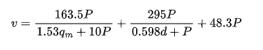
and the working allowable contact stress is :
The values of the coefficients are shown in Table 4.
| Parameter Meaning | Parameter Value | Parameter Meaning | Parameter Value |
|---|---|---|---|
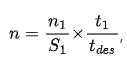
| Elastic Coefficient | 173.8 N/mm² | Stress Cycle Coefficient | 1.87 |
| Overload Coefficient | 1.0 | Hardness Ratio Coefficient | 1.0 |
| Dynamic Load Coefficient | 1.0 | Quality Coefficient | 1.0 |
| Contact Strength Calculation Load Distribution | 1.4 | Size Coefficient | 3.1 |
| Temperature Coefficient | 0.75 | Drum Shape Coefficient | 0.8 |
With an input power of 11 kW and a pinion rotational speed of 970 r/min, the torque is calculated as 108 N·m. Substituting these values into the formula, the contact stress is 1631 MPa.
4.2 Spiral Bevel Gear Contact Stress Field Analysis
Applying a torque of 108 N·m to the pinion and with a friction coefficient of 0.15, the maximum contact stress at the gear meshing point is 510 MPa through Simulation analysis, which is far less than the allowable contact stress of 1631 MPa. This indicates that under the warm forging process parameters of 600 °C and the given forging conditions, the contact stress of the formed spiral bevel gear is within the allowable range.
5. Conclusion
- Through simulation analysis of the forging under different warm forging temperatures (550 – 700 °C) and punch downward loads (1000 – 4000 N), the maximum stress and maximum displacement values of the spiral bevel gear during warm forging are obtained.
- By setting different warm forging billet temperatures and punch downward loads, 16 groups of data are simulated. To reduce the stress on the conical gear tooth surface and increase the deformation during forging, it is found that under the forging conditions of 600 °C and 4000 N, the maximum stress of the spiral bevel gear is reduced to 1548 MPa, and the maximum displacement is 0.2499 mm.
- The contact stress analysis at the meshing point of the designed spiral bevel gear verifies that the maximum contact stress of the warm forged spiral bevel gear is far less than the allowable contact stress value.
The research on the warm forging of spiral bevel gear provides valuable insights for optimizing the forging process, improving gear quality, and enhancing production efficiency. Future research could focus on further exploring the influence of other factors on the forging process and improving the accuracy of numerical simulations.