
Gear technology represents one of the most fundamental transmission mechanisms in mechanical engineering, with a history spanning over 2,400 years. As critical components for power transmission and speed modulation, gears permeate modern industry—from aerospace and marine engineering to micro-robotics and medical devices. Among emerging innovations in gear technology, point-line meshing gears have demonstrated exceptional potential due to their hybrid contact characteristics and superior performance metrics.
1 Development History
Point-line meshing gear technology originated in the 1990s through pioneering work by Professor Li Haixiang at Wuhan University of Technology. Over three decades, Professor Li’s team established fundamental design frameworks encompassing meshing theory, geometric parameterization, strength verification, and manufacturing protocols. Key milestones include:
- 1999: Wuhan Municipal Technology Invention Award
- 2001: Hubei Provincial Technology Invention Award
- National promotion as a key “Ninth Five-Year Plan” scientific project
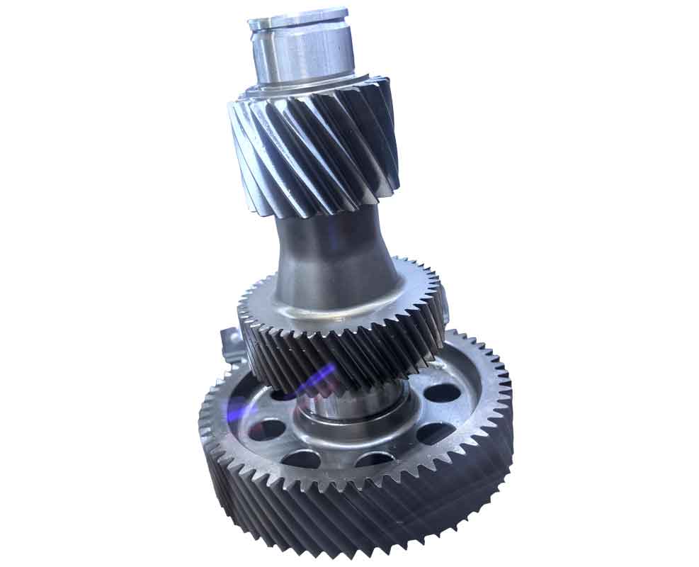
Unlike conventional involute or circular-arc gears, point-line meshing gears uniquely combine line contact and point contact during operation. The pinion features a modified involute profile with shortened teeth, while the gear exhibits a dual-profile design: an upper convex involute segment and a lower concave transition curve. This hybrid contact mechanism significantly enhances load capacity while reducing vibration and noise—addressing critical limitations in traditional gear technology.
2 Current Research Status
2.1 Geometric Parameter Design
Geometric optimization remains central to advancing point-line meshing gear technology. Critical parameters include helix angle, modification coefficients, tooth numbers, and module selection. The governing equations for meshing geometry are:
Transverse Mesh Stiffness: $$ K_t = \frac{\partial F}{\partial \delta} = \sum_{i=1}^{n} \frac{\partial F_i}{\partial \delta_i} $$
Parameter Selection Envelope: Developed by Luo et al., this framework constrains viable parameter combinations: $$ \beta_{\text{min}} \leq \beta \leq \beta_{\text{max}}, \quad x_1 + x_2 \geq x_{\text{sum, min}} $$ where $\beta$ denotes helix angle and $x_i$ represents modification coefficients.
| Parameter | Design Constraint | Performance Impact |
|---|---|---|
| Helix Angle ($\beta$) | 15°–30° | ↑ Contact ratio, ↓ axial vibration |
| Modification Coefficient ($x_1 + x_2$) | ≥ 0.8 | Prevents undercutting, ↑ bending strength |
| Pinion Tooth Count ($z_1$) | 12–25 | Balances size and stress concentration |
2.2 Strength Verification
Point-line meshing gear technology exhibits 15–93% higher strength metrics versus involute gears:
Contact Stress (Hertzian Theory): $$ \sigma_H = \sqrt{\frac{F_n}{\pi b} \cdot \frac{1/\rho_1 \pm 1/\rho_2}{(1-\nu_1^2)/E_1 + (1-\nu_2^2)/E_2}} $$ where $\rho_i$ = curvature radii, $E_i$ = elastic moduli, $\nu_i$ = Poisson’s ratios.
Bending Stress (Finite Element Model): $$ \sigma_F = \frac{K_A K_V K_{F\alpha} F_t}{b m_n} Y_{Fa} Y_{Sa} Y_\epsilon Y_\beta $$
| Strength Metric | Point-Line Gear | Involute Gear | Enhancement |
|---|---|---|---|
| Contact Strength | 1.5–1.93 × | 1.0 × | +93% max |
| Bending Strength | 1.1–1.15 × | 1.0 × | +15% max |
| Scoring Resistance | Integral Temp. Method | Flash Temp. Method | ↑ 20–30% |
2.3 Tooth Profile Optimization
Profile modifications are critical for dynamic performance. Optimal modification functions include:
Tip Relief Function: $$ C_{\text{mod}} = C_{\text{max}} \left[1 – \left(\frac{h – h_0}{h_1 – h_0}\right)^2\right] $$ where $C_{\text{max}}$ = maximum relief, $h$ = height from root.
Studies confirm 15–25% reductions in transmission error and mesh impact forces after optimization, significantly enhancing gear technology for high-speed applications.
2.4 Experimental Validation
Rigorous testing validates theoretical advances in point-line meshing gear technology:
- Load Capacity: 450 kN static load sustained in mine hoist upgrades (vs. 30 kN for involute systems)
- Noise Reduction: 5–7 dB(A) reduction in automotive transmissions
- Efficiency: 98.5–99.2% at rated loads, matching premium involute gear technology
2.5 Industrial Applications
| Industry Sector | Implementation | Performance Gain |
|---|---|---|
| Mining Machinery | Hoist gearboxes | ↑ 400% static load capacity |
| Automotive | Heavy-duty transmissions | ↓ 25% volume, ↓ 78 kg mass |
| Hydropower | Vertical kiln drives | ↑ 30% service life |
3 Future Research Prospects
While point-line meshing gear technology demonstrates clear advantages, three domains require intensified research:
Dynamics Modeling: Develop multi-body dynamic formulations accounting for time-varying mesh stiffness: $$ M\ddot{q} + C\dot{q} + K(t)q = F(t) $$ where $K(t)$ = periodic stiffness matrix.
Precision Manufacturing: Establish ISO-grade accuracy standards for dual-profile grinding processes to achieve AGMA 12+ tolerances.
Integrated Design Software: Create dedicated CAD/CAE platforms unifying parametric design, stress simulation, and topology optimization modules.
4 Conclusion
Point-line meshing gear technology represents a transformative advancement in power transmission systems. By synergizing the robustness of line contact with the stress distribution advantages of point contact, this innovation achieves unprecedented load density and acoustic performance. Current research has solidified foundational design methodologies, with experimental data confirming 15–93% strength improvements over involute systems. Future efforts must prioritize dynamic modeling, manufacturing precision, and digital toolchain development to unlock full industrial scalability. As these advancements mature, point-line meshing gears are poised to redefine high-performance gear technology across aerospace, energy, and transportation sectors.