
Abstract
In the internal gear honing process, residual stresses are generated on the workpiece surface after being machined by gear honing wheel. Due to the complexity of the factors contributing to residual stress formation, it is difficult to provide precise calculations using analytical methods. This paper utilizes Matlab, SolidWorks, and ANSYS/LS-DYNA software to conduct dynamic simulation analysis of the internal gear honing process. By extracting the analysis results, a data table of residual stress values at various special locations on the tooth surface is obtained. The analysis of the data indicates that the residual stress generated on the honed surface during internal gear honing is compressive, and its magnitude exhibits a certain variation pattern with different honing process parameters. Specifically, the residual stress decreases as gear honing speed increases, increases as gear honing force increases, and decreases within the range of variation of the shaft intersection angle as this angle increases. Finally, experiments verify the validity of the finite element analysis for predicting honing residual stresses.
1. Introduction
The internal gear honing method produces residual stresses on the honed surface layer, which can lead to stress corrosion resistance and tooth surface deformation in gears, reducing their fatigue strength. In severe cases, cracks may form on the tooth surface. To meet the demands of development, there is a need to predict the surface residual stresses in gears after processing and eliminate their impact, in order to save time in trial cutting during research and development, shorten the development cycle, and thereby reduce research costs. Obtaining a honed surface with a reasonable distribution of residual stresses by selecting appropriate honing conditions and controlling honing process parameters is of great significance for ensuring the quality and performance of high-precision gears.
Previous studies on residual stresses have mainly focused on numerical simulations of less complex 2D component processing, while there has been less research on residual stresses on the surfaces of gears with spatially complex curved surfaces. This paper investigates the residual stresses on the surface of workpieces subjected to internal gear honing using the finite element simulation method.
2. Methodology
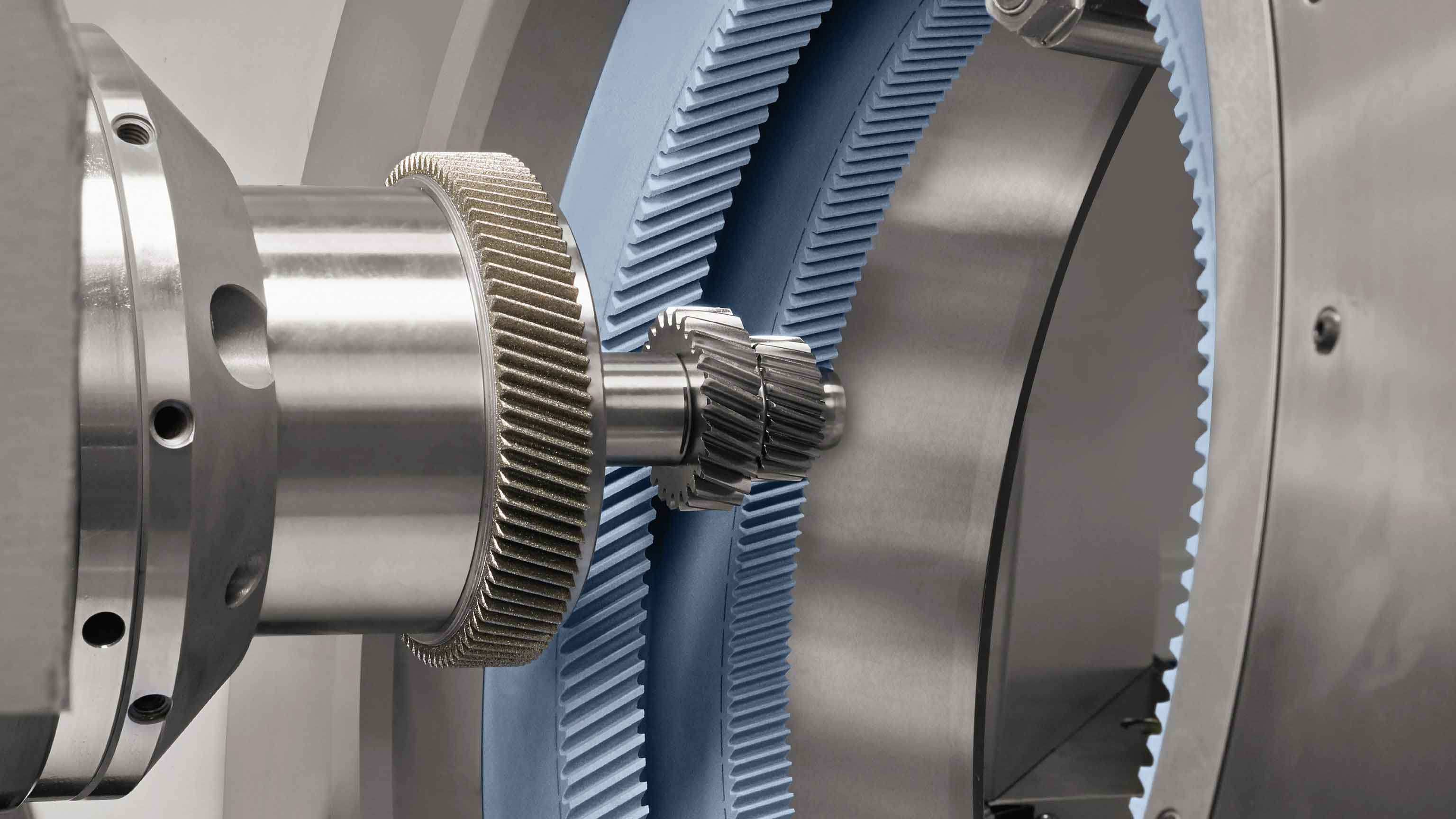
2.1 Geometric Model Import and Simplification
Before importing the geometric model, the assembly needs to be adjusted to a position of contact but without interference. In dynamic solving, it can be considered that the solution begins from this position, and the entire dynamic process also begins to iterate from this position.
2.2 Finite Element Simulation Process
The finite element calculation process for gear honing residual stresses mainly consists of the following two steps:
- Define structural constraints and apply radial forces to obtain the distribution of equivalent stress fields during gear honing.
- The formation process of residual stresses, i.e., removing all loads and importing the equivalent stress during gear honing process as the initial stress to solve for the residual stresses.
3. Simulation Results and Analysis
3.1 Influence of Honing Speed on Residual Stress
Under the conditions of a shaft intersection angle of 8.722° and gear honing radial force of 150 N, the rotational speed of the workpiece was varied. The distribution of residual stresses obtained through finite element simulation at workpiece rotational speeds of 60.08, 90.12, 120.16, 150.16, and 180.24 rad/s is shown in Figure 8.
| Rotational Speed (rad/s) | Residual Stress (MPa) |
|---|---|
| 60.08 | σ1 |
| 90.12 | σ2 |
| 120.16 | σ3 |
| 150.16 | σ4 |
| 180.24 | σ5 |
3.2 Influence of Honing Radial Force on Residual Stress
Under the conditions of a shaft intersection angle of 8.722° and gear honing wheel and workpiece rotational speeds of 151.67 and 90.12 rad/s, respectively, the magnitude of gear honing radial force was varied. The distribution of gear honing residual stresses obtained through finite element simulation at honing radial forces of 150, 300, 450, 600, 750, and 1000 N is shown in Figure 9. It can be seen from Figure 9 that gear honing residual stresses at various locations increase to varying degrees as gear honing radial force increases.
| Honing Radial Force (N) | Residual Stress (MPa) |
|---|---|
| 150 | σ1 |
| 300 | σ2 |
| 450 | σ3 |
| 600 | σ4 |
| 750 | σ5 |
| 1000 | σ6 |
3.3 Influence of Shaft Intersection Angle on Residual Stress
Under the conditions of gear honing wheel and workpiece rotational speeds of 151.67 and 90.12 rad/s, respectively, and gear honing radial force of 150 N, the magnitude of the shaft intersection angle was varied. Three-dimensional models of internal gear honing wheels with different helix angles were created at shaft intersection angles of 8°, 10°, 12°, 14°, and 16°, and the distribution of gear honing residual stresses obtained through finite element simulation is shown in Figure 10.
| Shaft Intersection Angle (°) | Residual Stress (MPa) |
|---|---|
| 8 | σ1 |
| 10 | σ2 |
| 12 | σ3 |
| 14 | σ4 |
| 16 | σ5 |
4. Experimental Validation
The X-ray diffraction method was selected for testing honing residual stresses, using a Rigaku D/MAX 2550 18 kW rotating anode X-ray diffractometer. Before the experiment, a tooth sample was cut out from the workpiece gear below the tooth root circle using wire electrical discharge machining. The gear honing conditions used during processing were consistent with those used in the finite element simulation. Under wet grinding conditions, the rotational speeds of the gear honing wheel and workpiece were 151.67 and 90.12 rad/s, respectively, and the shaft intersection angle was 8.722°. During the experiment, a Cu target radiation source was used, with an X-ray wavelength λ = 0.15406 nm, tube current of 30 mA, and tube voltage of 40 kV.
Residual stresses were measured at the same six unit locations as in the simulation, as shown in Figure 11. The comparison between the measured and simulated values of gear honing residual stresses is listed in Table 3.
| Unit Location | Measured Residual Stress (MPa) | Simulated Residual Stress (MPa) | Relative Error (%) |
|---|---|---|---|
| 55621 | σm1 | σs1 | ε1 |
| 56606 | σm2 | σs2 | ε2 |
| 56586 | σm3 | σs3 | ε3 |
| 56326 | σm4 | σs4 | ε4 |
| 56926 | σm5 | σs5 | ε5 |
| 55286 | σm6 | σs6 | ε6 |
The maximum relative error between the measured and simulated values of gear honing residual stresses was 13.6%. This indicates that the finite element method has good accuracy and provides a certain reference for controlling the residual stresses in honed gear workpieces.
5. Conclusion
This paper presents a study on the residual stresses on the surface of workpieces subjected to internal gear honing. The tooth surface equation of the internal gear honing wheel was derived based on the conjugate principle of the internal gear honing wheel and workpiece. Data points on the tooth surface were obtained in Matlab and imported into SolidWorks to obtain a three-dimensional model of the internal gear honing wheel. Elastic-plastic theory and numerical finite element calculation methods were used to analyze the constraint conditions and boundary conditions. The dynamic meshing process between the internal gear honing wheel and the workpiece was simulated in LS-PrePost software to solve for the residual stresses. The simulation results show that the residual stresses on the workpiece surface after honing are compressive and exhibit a certain variation pattern with different honing process parameters. Specifically, the residual stresses decrease as the workpiece rotational speed increases, increase as gear honing radial force increases, and decrease as the shaft intersection angle increases. The experimental validation using the X-ray diffraction method demonstrates that the finite element method has good accuracy, providing a certain reference for controlling the residual stresses in honed gear workpieces.