
In the realm of manufacturing automation, the transformation of traditional machine tools through digital control systems represents a pivotal advancement. My extensive involvement in this field has centered on enhancing the capabilities of gear production equipment, specifically targeting the precise and efficient machining of helical bevel gears. These components are critical in automotive systems, such as steering mechanisms, where their quality directly impacts performance and safety. The original text describes a retrofit project using an STD bus industrial control computer to modify a数控滚齿机 (a gear hobbing machine), enabling it to machine spiral bevel gears with improved accuracy. This article elaborates on that foundation, expanding into a comprehensive technical discourse from my first-person perspective, delving into hardware architecture, software engineering, mathematical modeling, and practical implementation for helical bevel gear production.
The core challenge addressed was the inherent limitation of conventional gear hobbing machines, which typically lack the coordinated control between radial and vertical feed axes necessary for generating conical geometries like those of helical bevel gears. In my project, the objective was to retrofit such a machine to achieve this axis interpolation, thereby allowing it to produce high-precision helical bevel gears with complex, involute tooth profiles. The solution hinged on replacing the legacy control system with a modular, reliable STD bus-based industrial computer system. This approach not only preserved the machine’s primary functions for spur and helical cylindrical gears but also unlocked new capabilities for manufacturing intricate helical bevel gears, which are essential for advancing domestic automotive component quality and reducing reliance on imports.
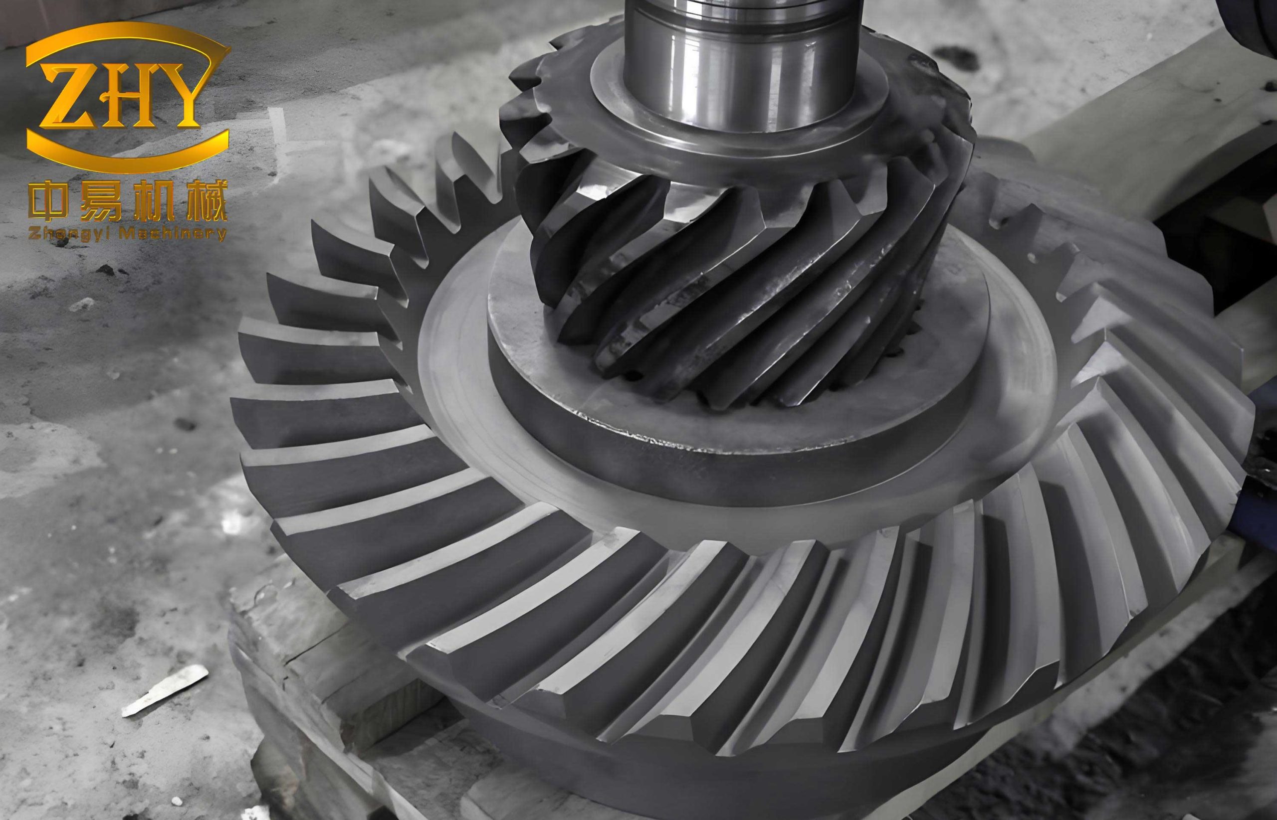
The selection of helical bevel gears as the focal point is deliberate due to their geometric complexity and industrial significance. Their tooth surfaces are three-dimensional, requiring synchronized motion along multiple axes to accurately trace the involute curve across a conical surface. My retrofit system was designed specifically to master this synchronization, making the production of helical bevel gears both feasible and precise on upgraded equipment. Throughout this narrative, the term helical bevel gears will be frequently emphasized to underscore the specific application and technical challenges overcome.
System Hardware Architecture and Design
From my design experience, the hardware foundation is paramount for any industrial control system. The retrofitted control system is built around an STD 5000 series industrial control computer, chosen for its ruggedness, modularity, and proven performance in factory environments. The system’s hardware structure, as I implemented it, can be summarized in the following block diagram and detailed table.
The heart of the system is the CPU module. I utilized an Intel 8088 16-bit microprocessor running at 12 MHz. This choice provided a balance between processing power for real-time control tasks and compatibility with the STD bus ecosystem. The memory configuration included 256 KB of RAM with battery-backed protection for storing user part programs and system parameters, alongside EPROM sockets for housing the firmwcontrol software and a dedicated Chinese character library for the operator interface. The use of paged addressing mode enhanced memory access speed, crucial for real-time interpolation calculations.
For human-machine interaction, I integrated a dedicated display and keyboard interface board. This board supported multiple display standards (MDA/CGA/Hercules) and facilitated the connection of a CRT monitor for graphical and textual feedback. All operational prompts, menus, and status information were displayed in Chinese characters, greatly simplifying the operator’s task. A standard parallel printer port and keyboard interface were also implemented using additional logic chips like the 74HCT373 under the control of a dedicated controller chip.
The servo drive system employed stepper motors for both the radial (X-axis) and vertical (Y-axis) feed mechanisms. Stepper motors were selected for their cost-effectiveness, simplicity, and open-loop control suitability for this precision level. The control signals generated by the STD computer’s digital output modules were isolated using high-speed optocouplers before being sent to the stepper motor driver amplifiers. This opto-isolation was a critical design decision I made to protect the sensitive computer electronics from electrical noise, spikes, and ground loops prevalent in the industrial machine tool environment, thereby significantly boosting system reliability.
The following table details the key hardware components and their specifications as deployed in my helical bevel gear machining retrofit system:
| Component Category | Specific Model/Type | Key Specifications & Function |
|---|---|---|
| Main CPU Board | STD-8088 based CPU Card | Intel 8088 @ 12MHz, 256KB RAM with battery backup, EPROM sockets, Page-mode addressing. |
| Man-Machine Interface | Custom Display/Keyboard I/O Card | Supports CRT with Chinese character library (CGA/Hercules modes), integrated keyboard interface, parallel printer port. |
| Digital I/O Modules | STD Digital Input/Output Cards | For reading limit switches, control panel inputs; outputting pulse/direction signals for stepper drivers. All channels optically isolated. |
| Servo Actuators | Two-phase Hybrid Stepper Motors | Connected to X (radial) and Y (vertical) axis ball screws. Selected based on required torque and step resolution. |
| Drive Electronics | Stepper Motor Driver Amplifiers | Receive isolated pulse/direction signals, provide high-current phase windings to drive the stepper motors. |
| Machine Interface | Relay & Contactor Panel | Interfaced via I/O cards to control spindle motor (forward/reverse), coolant pump, lubrication, and other auxiliary functions of the original hobbing machine. |
This modular hardware architecture, based on the STD bus, offered immense flexibility. It allowed me to prototype, test, and debug subsystems independently. Furthermore, it simplified maintenance and future upgrades—a failing I/O card could be swapped without affecting the entire system. The robustness of this design was proven in the harsh electrical environment of the machine shop, ensuring stable operation for the precise machining of helical bevel gears.
Software System Design and Functionality
The software is the intelligence that breathes life into the hardware. My approach to the control software was to develop a structured, menu-driven application in 8088 assembly language to ensure execution speed and direct hardware control. Upon system power-up or reset, the software automatically initializes and presents a main menu screen with Chinese prompts. The software architecture is modular, encompassing several key operational modes tailored for the machining of helical bevel gears and other gears.
The primary software modes I implemented are:
- Parameter Setting & Program Editing: This mode allows the operator to input, modify, store, and delete part programs. Programs for helical bevel gears include geometric parameters (module, number of teeth, pressure angle), tool data, and feed rates. The interface uses forms and prompts to guide input.
- Manual Operation (Jog) Mode: This mode provides manual control for setup and tooling. The operator can jog the X and Y axes independently in positive or negative directions at adjustable speeds. Functions like coolant on/off, spindle start/stop, and a “return-to-zero” sequence for homing the axes are also accessible here.
- Automatic Cycle (Machining) Mode: This is the core production mode. The operator selects a stored part program (e.g., for a specific helical bevel gear), and the system loads it into the active memory area. The control then executes the program, managing the coordinated motion of X and Y axes, spindle rotation, and auxiliary functions in real-time. A dynamic status display shows the current position, feed rate, and active commands.
The software flow, from my design documentation, follows a logical sequence to manage these modes and real-time interrupts for axis control. A simplified representation of the main program flow is as follows:
- System Initialization (Hardware ports, variables, display).
- Display Start-up Screen & Main Menu.
- Enter Key Scanning Loop.
- If “Parameter Setting” selected → Enter Editor Subroutine.
- If “Manual Mode” selected → Enter Jog Control Subroutine.
- If “Cycle Start” selected → Load Program → Enter Automatic Interpolation & Control Loop.
- Within the Automatic Loop: Continuously execute interpolation calculations, update axis motor pulses, monitor inputs, and refresh the display until program end or stop command.
The real-time kernel for axis control uses timer interrupts to generate precise pulse trains for the stepper motors. The critical task here is the interpolation algorithm, which calculates the intermediate points along the desired tool path. For machining helical bevel gears, this involves complex curve interpolation, which I will detail in the next section.
Mathematical Modeling and Interpolation for Helical Bevel Gear Tooth Profiles
The most technically demanding aspect of this retrofit was developing the software routines to generate the precise tool path required for the involute tooth profile of a helical bevel gear. Standard数控 (CNC) interpolation algorithms like the digital differential analyzer (DDA) or Bresenham’s line algorithm are excellent for lines and circles but are insufficient for a true three-dimensional involute on a cone. My solution involved deriving the tool path from the fundamental geometry of the gear and implementing a computationally efficient algorithm.
For a standard involute curve on a spur gear, the parametric equations are well-known. However, for a helical bevel gear, the geometry is more complex because the tooth is both inclined (helix) and on a conical surface (bevel). In my project, to simplify initial control complexity while achieving functional helical bevel gear production, the primary focus was on generating the tapered (conical) involute profile. The helix aspect was partly addressed by the inherent setup of the hobbing process and machine kinematics, but the critical software control was the synchronized X-Y motion to create the taper. This synchronization ensures that the ratio of vertical feed (S_v) to radial feed (S_r) is constant and equal to the tangent of the cone angle (α), i.e.,
$$ \tan(\alpha) = \frac{S_v}{S_r} $$
In the digital control domain, feeds are achieved by issuing pulse streams to the stepper motors. Therefore, controlling the pulse frequencies for the Y-axis (vertical) and X-axis (radial) drivers, denoted as $f_v$ and $f_r$ respectively, directly controls the feed rates. The relationship must satisfy:
$$ \frac{f_v}{f_r} = K \cdot \tan(\alpha) $$
where $K$ is a constant scaling factor relating pulse frequency to linear axis velocity (determined by screw lead and motor step angle).
The tooth profile itself is an involute. The first step in my algorithm was to calculate key geometric parameters of the helical bevel gear (simplified to its profile at a mean cone distance). Given the module ($m$), number of teeth ($z$), and pressure angle ($\phi$, typically 20°), we compute:
- Pitch Diameter: $d = m \cdot z$
- Base Diameter: $d_b = d \cdot \cos(\phi)$
- Addendum Diameter: $d_a = m \cdot (z + 2)$
- Dedendum Diameter: $d_f = m \cdot (z – 2.5)$
Corresponding radii are: $r = d/2$, $r_b = d_b/2$, $r_a = d_a/2$, $r_f = d_f/2$.
The involute curve is defined in polar coordinates (radius $ρ$, angle $\theta$) relative to the base circle. A point on the involute is given by:
$$ \theta(ρ) = \frac{\sqrt{ρ^2 – r_b^2}}{r_b} – \arccos\left(\frac{r_b}{ρ}\right) $$
or sometimes equivalently using the involute function: $\text{inv}(\phi) = \tan(\phi) – \phi$.
To generate the tool path, I discretized the radial distance from the start of the active profile (near $r_f$) to the tip ($r_a$). For each discrete radius $ρ_i$, the corresponding polar angle $\theta_i$ was calculated using the above formula. These polar coordinates were then transformed into Cartesian coordinates for the machine’s X-Y plane (representing radial and vertical axes on the conical projection):
$$ x_i = ρ_i \cdot \cos(\theta_i) $$
$$ y_i = ρ_i \cdot \sin(\theta_i) $$
However, for a helical bevel gear, this $x_i$ and $y_i$ are not directly the machine X and Y coordinates. They represent coordinates on a plane normal to the cone generatrix. The machine X (radial) and Y (vertical) motions must be scaled and synchronized to map this 2D involute onto the conical surface. The required mapping involves compensating for the cone angle. If we consider the developed tooth profile on a back-cone, the relationship between the profile coordinates ($x_p$, $y_p$) and machine axis displacements ($\Delta X$, $\Delta Y$) can be expressed as:
$$ \Delta X = x_p \cdot \cos(\alpha) + y_p \cdot \sin(\alpha) \cdot C $$
$$ \Delta Y = -x_p \cdot \sin(\alpha) + y_p \cdot \cos(\alpha) \cdot C $$
where $C$ is a scaling factor relating the profile plane to the machine’s axial travels, and $\alpha$ is the pitch cone angle. The exact transformation depends on the specific machine kinematics. In my implementation, this was simplified into a synchronized two-axis linear interpolation where the commanded path in the X-Y plane was a scaled version of the calculated involute, with the axis ratio fixed by $\tan(\alpha)$. The software routine, written in optimized 8088 assembly, pre-computed a table of ($\Delta X$, $\Delta Y$) coordinate pairs for the tooth flank and then used a linear interpolator between these points in real-time, ensuring the tool followed the correct path to generate the helical bevel gear tooth space.
The following table summarizes the key parameters and formulas used in the geometric calculation for a typical helical bevel gear setup in my system:
| Parameter Symbol | Description | Formula / Calculation |
|---|---|---|
| $m$ | Module | Given (design parameter for helical bevel gears). |
| $z$ | Number of Teeth | Given. |
| $\phi$ | Pressure Angle | Usually 20°. |
| $d$ | Pitch Diameter | $d = m \cdot z$ |
| $d_b$ | Base Diameter | $d_b = d \cdot \cos(\phi)$ |
| $\alpha$ | Pitch Cone Angle | Derived from gear ratio and shaft angle (e.g., for a 1:1 bevel, $\alpha = 45°$ for 90° shaft angle). |
| $S_v/S_r$ | Feed Ratio | $\tan(\alpha)$ |
| $f_v/f_r$ | Pulse Frequency Ratio | Proportional to $\tan(\alpha)$, scaled by mechanical constants. |
| $\rho$ | Variable Radius (from $r_f$ to $r_a$) | Discretized over the active profile. |
| $\theta(\rho)$ | Involute Polar Angle | $\theta = \frac{\sqrt{\rho^2 – r_b^2}}{r_b} – \arccos(r_b/\rho)$ |
System Integration, Testing, and Performance
Integrating the hardware and software into a cohesive, reliable system was an iterative process. After assembling the STD card cage, wiring the opto-isolated I/O to the machine’s limit switches, relays, and stepper drivers, and loading the control software into EPROM, the commissioning phase began. I conducted extensive tests, starting with verifying each I/O point, then testing axis movement in manual mode, and finally running simulated and actual cutting cycles for helical bevel gears.
A critical test was the “dry run” or air-cut, where the machine executes the program without a workpiece. Using this, I verified the synchronized motion of the X and Y axes, ensuring the tool path produced the correct taper corresponding to the cone angle of the helical bevel gear. The graphical display proved invaluable here, showing real-time position updates.
Subsequent production trials involved machining actual helical bevel gear blanks from steel. The performance metrics focused on:
- Accuracy: The dimensional accuracy of the machined gears was measured using gear checking instruments. The results showed that the retrofitted system could hold tolerances well within the requirements for automotive applications, particularly for the critical involute profile and tooth spacing. The repeatability of the stepper system, when properly sized and driven, was excellent.
- Surface Finish: The smooth interpolation and consistent feed rates resulted in a good surface finish on the tooth flanks of the helical bevel gears, reducing the need for secondary finishing operations.
- Reliability: The industrial-grade components and extensive use of opto-isolation led to a very low failure rate. The system operated stably over extended production runs in a typical workshop environment with electrical noise and vibration.
- Usability: Operators familiar with the old machine quickly adapted to the new system due to the intuitive Chinese menu system. Programming new helical bevel gear jobs became a matter of entering parameters rather than designing complex mechanical change gears.
The successful machining of helical bevel gears on this retrofitted machine validated the entire design approach. It demonstrated that with a carefully designed STD bus control system, even machines not originally intended for such tasks could be upgraded to produce high-value, complex components like helical bevel gears.
Broader Implications and Concluding Remarks
This retrofit project, from my perspective, exemplifies a practical and cost-effective strategy for technological modernization in manufacturing. For small and medium-sized enterprises (SMEs) that cannot afford brand-new, multi-axis CNC gear cutting machines, such a retrofit offers a viable path to enhance capability and product quality. The ability to produce precision helical bevel gears domestically has significant economic implications, reducing import dependency and strengthening the supply chain for industries like automotive.
The choice of the STD bus was instrumental. Its modular nature allowed for a tailored system that exactly met the control needs for helical bevel gear machining without over-engineering. While newer bus standards like PCI or PCIe exist, the simplicity, robustness, and availability of STD components made it ideal for this industrial retrofit. The software, though written in assembly for efficiency, was structured to be maintainable and could theoretically be ported to a higher-level language for future iterations.
In conclusion, the integration of an industrial control computer based on the STD bus into a conventional gear hobbing machine transforms it into a flexible, precise, and user-friendly platform for manufacturing helical bevel gears. The system’s design, encompassing hardened hardware, intelligent software with specialized interpolation routines for involute curves, and a clear operator interface, directly addresses the challenges of machining these complex components. The project underscores that through thoughtful engineering retrofits, existing capital equipment can be extended in functionality and lifespan, contributing significantly to productivity and technological self-reliance in precision gear manufacturing. The focus on helical bevel gears throughout this endeavor highlights a specific and valuable application area where such control system upgrades can yield immediate and substantial benefits.