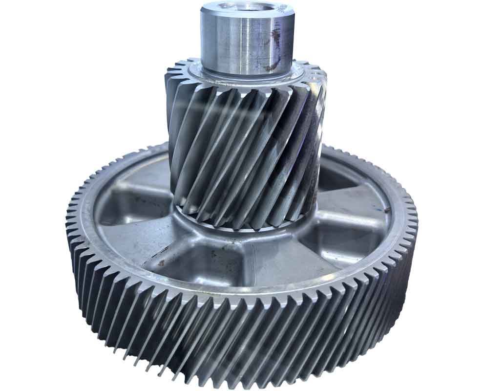
Precision in surveying involute cylindrical spur gears is critical for restoring original design parameters of reverse gears. Integrating reverse engineering into gear metrology enhances measurement accuracy and provides robust validation tools. This approach is particularly valuable when reverse gear components face extended procurement cycles or obsolescence.
Reverse engineering reconstructs digital models from physical artifacts through two primary phases: data acquisition via 3D scanning and computational model development. For reverse gear applications, structured-light scanners capture micron-level surface details, generating dense point clouds for subsequent processing.
Fundamental Parameter Acquisition
Essential reverse gear measurements include:
- Tooth count (Z)
- Tip diameter (da)
- Root diameter (df)
- Base tangent lengths (Wk, Wk-1)
- Operating center distance (a’)
Conventional metrology uses micrometers and gear calipers, while reverse engineering employs point-cloud processing for direct parameter extraction:
$$d_a = \frac{\sum_{i=1}^{n} \|P_{a_i} – O\|}{n} \times 2, \quad d_f = \frac{\sum_{i=1}^{m} \|P_{f_j} – O\|}{m} \times 2$$
where Pa and Pf denote tip/root cloud points, O represents the gear centroid, and n/m are averaging samples.
Geometric Parameter Determination
Module (m), pressure angle (α), addendum coefficient (ha*), and dedendum coefficient (c*) are derived through reverse gear standards analysis and computational formulas independent of profile shifts:
$$d_a – d_f = 2(2h_a^* + c^*)m$$
$$P_b = W_k – W_{k-1} = \pi m \cos\alpha$$
| Standard | Pressure Angle (°) | ha* | c* | Application Region |
|---|---|---|---|---|
| ISO 53 | 20 | 1.0 | 0.25 | Global |
| ASA B6.1 | 20/25 | 1.0 | 0.35 | North America |
| DIN 867 | 20 | 0.8-1.0 | 0.1-0.5 | EU |
Profile Shift Validation Techniques
Reverse engineering enables dual validation methodologies for reverse gear parameters:
1. Tooth Profile Correlation
Point-cloud data is processed through computational geometry algorithms:

$$x = \frac{h_a – h_a^*m}{m}, \quad \alpha_{\text{meas}} = \cos^{-1}\left(\frac{d_b}{d}\right)$$
where db is base diameter, d is reference diameter, and αmeas is derived pressure angle.
2. Meshing Pair Verification
Conjugate gear analysis ensures kinematic consistency:
$$a’ = \frac{m}{2}(Z_1 + Z_2) + m(x_1 + x_2)$$
$$x_1 + x_2 = \frac{a’ – a}{m}, \quad a = \frac{m}{2}(Z_1 + Z_2)$$
Industrial Case Implementation
A mining reverse gear (Z=16) was analyzed using reverse engineering protocols:
| Parameter | Measured (mm) | Calculated (mm) | Deviation (%) |
|---|---|---|---|
| da | 93.98 | 93.72 | 0.28 |
| df | 70.05 | 69.84 | 0.30 |
| W3 | 39.36 | 39.31 | 0.13 |
Validation outcomes confirmed DP=5 (m=5.08mm), α=25°, x=0.225. Conjugate gear analysis (Z=49) demonstrated kinematic consistency with center distance error <0.02%.
Conclusion
Reverse engineering transforms reverse gear metrology by enabling non-contact measurement, computational validation, and digital twin generation. The integration of point-cloud analytics with kinematic verification protocols ensures parameter reconstruction accuracy within 0.3% tolerance. This methodology significantly enhances reverse gear reproduction fidelity while reducing dependence on OEM documentation.
