
1. Reverse engineering inspection process
Firstly, the digital model of the specified workpiece is obtained through the three-dimensional optical scanning system, and then the digital model is processed to measure the key dimensions; In addition, the physical model of the workpiece can also be compared with the digital model in an all-round way to generate a complete inspection report for detailed analysis.
2. Acquisition and processing of reverse engineering point cloud data
After spraying the small module gear to dry, it is fixed on the rotary worktable with rubber mud, then adjust the position of the universal platform and the probe, and then click the turntable to measure. Set the number of times to be measured and exposure parameters. After the equipment is adjusted in place, scan the part data to obtain the reverse engineering point cloud data.
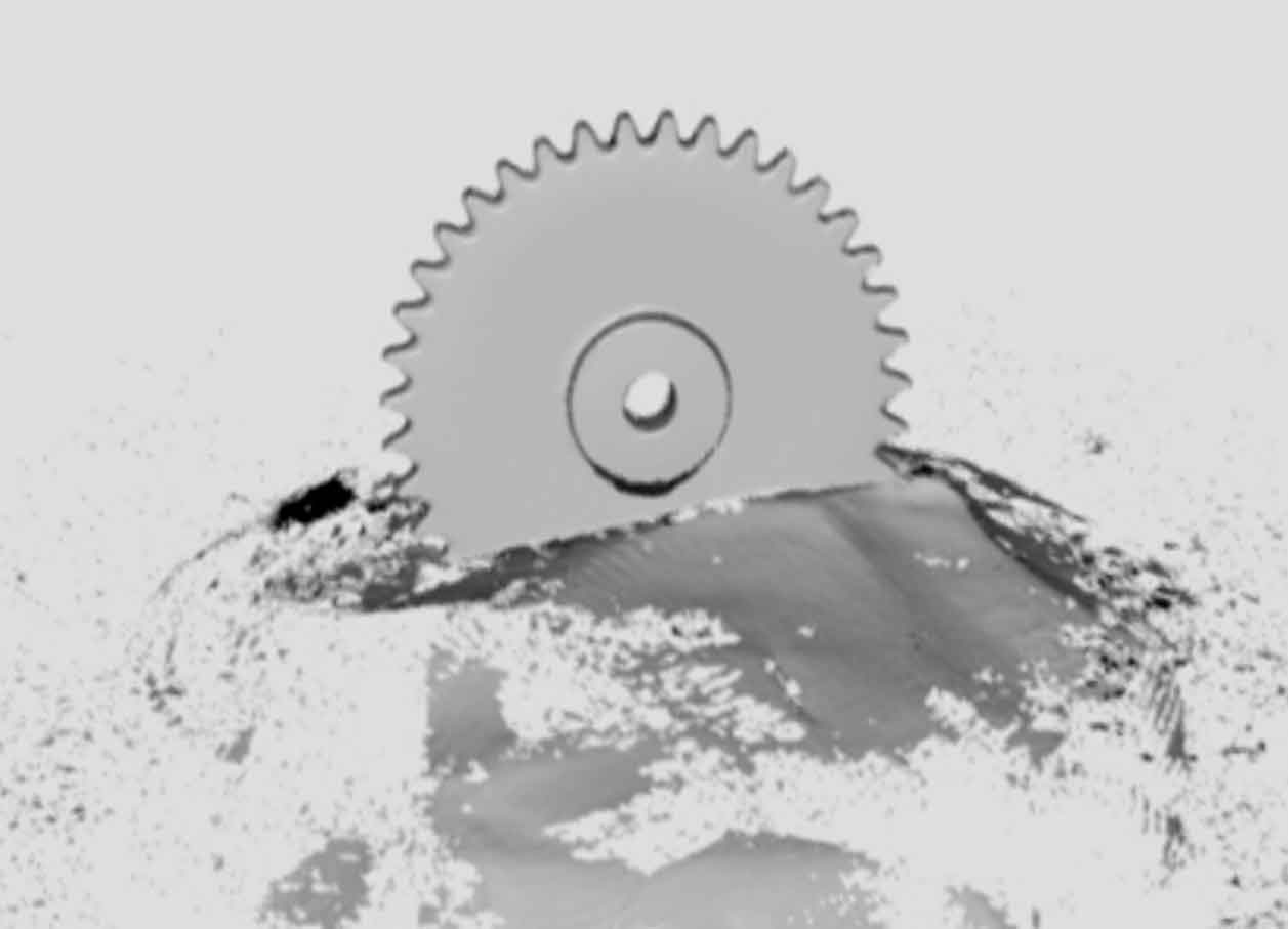
The data model completed by reverse engineering scanning is shown in Figure 1.
Export the obtained reverse engineering point cloud data to triangular surface format (STL format), and then import it into Geomagic studio for subsequent processing. The main purpose of this move is to remove the noise points in the process of data acquisition and delete the reverse engineering point cloud data outside the part entity.

The processed small module gear data (grid data) is shown in Figure 2.
3. Alignment and analysis
Save the model processed in the previous step as STL format, import the CAD data and scanning results of the original model of small module gear into Geomagic control x, and use the N-point alignment command to align the original model with the scanned model.

The 3D scanner is used for scanning comparison, and the comparison results are shown in Figure 3.
The difference of color depth shows the difference of deviation, and the color difference diagram intuitively shows the size deviation of small module gear; Then the author creates notes for specific parts, and can directly observe the deviation of a small module gear. Because only the impurity points are removed from the reverse engineering point cloud data, the model accuracy will not be affected. The model accuracy is determined by the scanning accuracy of the data acquisition equipment.
As can be seen from Figure 3:
(1) there is a deviation in the Y direction of the boss position in the middle of A007 gear, which is mainly caused by the large thickness of this position and uneven material shrinkage;
(2) A004, A005 and a006 also have different degrees of deviation, which is closely related to the internal stress caused by material shrinkage and is also affected by the number and arrangement of supports during printing, but these errors will not affect the transmission accuracy of gears; A001, a002 and a003 are close to the gear teeth. The shrinkage and deformation of the material at the most edge are more obvious, mainly due to the small thickness of the whole gear.
Compared with ordinary processing methods, the processing of small module gears has strict requirements, and even some traditional metal processing methods can not produce standard small module gears at all.
The small module gear is manufactured quickly and accurately by SLA light curing technology; At the same time, for the problem that it is difficult to detect the small module gear, the data acquisition and model reconstruction of the manufactured products are carried out through the three-dimensional scanner, the reconstructed model is compared with the original design model data, and the manufacturing error of the small module gear is detected from the three-dimensional direction, which explores a new way for the detection of the small module gear, It also provides a new idea for the digital manufacturing and testing of small-scale complex parts.