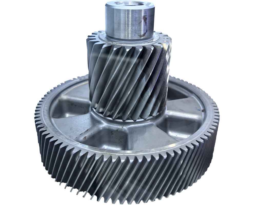
Reverse engineering techniques enable precise reconstruction of gear morphology for tribological enhancement. The process begins with non-contact 3D laser scanning using a 3D SCANNER system (maximum volume: 550×450×450mm; accuracy: 0.2mm). Before scanning, gear surfaces undergo whitening treatment with DPT-5 developer to optimize reflectivity. Partial scanning exploits gear symmetry, with subsequent full-gear reconstruction through mirroring operations in Surfacer software.

Critical point-cloud processing includes noise removal and feature extraction:
| Processing Stage | Surfacer Function | Objective |
|---|---|---|
| Noise Removal | Point/Extract Points/Circle-Select | Eliminate platform/interference points |
| Feature Fitting | Curve/Construct3D/Circle/3 Point | Establish reference geometry (center: 0,0,0) |
| Surface Reconstruction | Surface/Transition/Merge Surface | Seamless tooth surface integration |
The reconstructed surface undergoes conversion to solid model via IGES export to UG-NX software. This reverse gear reconstruction pipeline enables parametric extraction of critical dimensions:
$$
\begin{cases}
z = \text{Number of teeth} \\
d_a = \text{Tip diameter} \\
d_f = \text{Root diameter} \\
p = \text{Pitch}
\end{cases}
$$
Bionic Non-Smooth Surface Design and Laser Processing
Biological analysis reveals soil organisms like dung beetles employ concave morphologies for wear resistance. Nine pit configurations were derived for reverse gear applications:
| Design | Diameter (μm) | Row Spacing (μm) | Column Spacing (μm) |
|---|---|---|---|
| Pit 1 | 200 | 350 | 700 |
| Pit 2 | 200 | 550 | 700 |
| Pit 3 | 250 | 450 | 750 |
| Pit 4 | 300 | 350 | 800 |
| Pit 5 | 300 | 550 | 800 |
Laser texturing employed JHM-1GY-100B equipment with YAG laser (λ=1.06μm, max pulse energy=50J). Key processing parameters:
$$
\begin{array}{c|c|c}
\text{Parameter} & \text{Symbol} & \text{Value} \\
\hline
\text{Focal length} & f & 55\text{mm} \\
\text{Pulse width} & t_p & 10-15\text{ms} \\
\text{Scanning speed} & v_s & 99-163\mu\text{m/s} \\
\text{Peak current} & I_p & 130-180\text{A}
\end{array}
$$
Surface transformation occurred through melt-pool dynamics governed by power density thresholds:
$$
\begin{cases}
\text{Melting: } I \geq 10^4 \text{W/cm}^2 \\
\text{Vaporization: } I \geq 10^7 \text{W/cm}^2
\end{cases}
$$
Micro-Tribological Evaluation
Orthogonal testing (L₁₆(2¹⁵)) evaluated wear performance on CETR UMT tribometer with GCr15 counterbody (HRC 63, Ø4mm). Test matrix:
| Factor | Level -1 | Level 0 | Level 1 |
|---|---|---|---|
| Size (z₁, μm) | 200 | 250 | 300 |
| Spacing (z₂, μm) | 350 | 450 | 550 |
| Speed (z₃, rpm) | 80 | 110 | 140 |
| Load (z₄, N) | 7 | 10 | 13 |
Volume wear rate (K) quantification:
$$
\Delta V = a \left[ \frac{r^2}{2} \arcsin\left(\frac{d}{2r}\right) – \frac{d}{4} \sqrt{4r^2 – d^2} \right]
$$
$$
K = \frac{\Delta V}{L \times T} \quad (\text{μm}^3/\text{N·min})
$$
where d = wear scar width, r = 2mm ball radius, a = 20mm sliding distance, L = load, T = 90min duration.
Non-smooth surfaces demonstrated superior wear resistance over conventional gears:
| Configuration | Max Q (%) | Min Q (%) | Critical Parameters |
|---|---|---|---|
| Pit 4 | 135.39 | 42.83 | z₁=300μm, z₂=350μm |
| Pit 2 | 8.86 | 7.22 | z₁=200μm, z₂=550μm |
Wear mechanisms combined adhesive and abrasive modes with debris entrapment in concavities. Optimal reverse gear performance occurred at low velocity (80rpm) and light load (7N) for Pit 4 configuration.
Regression Modeling of Wear Behavior
Multi-linear regression yielded predictive equations for volume wear rate (ŷ₁) and friction coefficient (ŷ₂):
$$
ŷ_1 = 7.0829 \times 10^5 – 1.1927 \times 10^3 z_1 + 8.117 \times 10^3 z_2 + 4.65 \times 10^3 z_3 + 8.9637 \times 10^4 z_4 + 1.1783 \times 10^{-4} z_2 z_3
$$
$$
ŷ_2 = 0.946 + 1.965 \times 10^{-4} z_1 – 6.076 \times 10^{-4} z_2 – 1.494 \times 10^{-3} z_3 – 7.265 \times 10^{-2} z_4 + 1.883 \times 10^{-5} z_2 z_4 + 7.750 \times 10^{-5} z_3 z_4
$$
Factor significance ranking:
- Volume wear: Load (z₄) > Speed (z₃) > Size (z₁) > Spacing (z₂)
- Friction: Load (z₄) > Speed (z₃) > Spacing (z₂) > Size (z₁)
Interaction effects remained below significance threshold (F<1), validating model robustness for reverse gear optimization.
Conclusion
Reverse engineering enables precise reconstruction of gear morphology for surface enhancement. Concave non-smooth geometries (300μm diameter/350μm spacing) fabricated via YAG laser texturing improve wear resistance by 135.4% through combined mechanisms: laser-induced martensitic transformation (hardness increase) and debris entrapment. Wear rate follows positive correlation with load/speed (R²=0.964), while friction coefficient exhibits inverse dependence. The regression models provide predictive tools for reverse gear surface optimization across operational conditions, demonstrating significant potential for industrial applications requiring enhanced durability.
