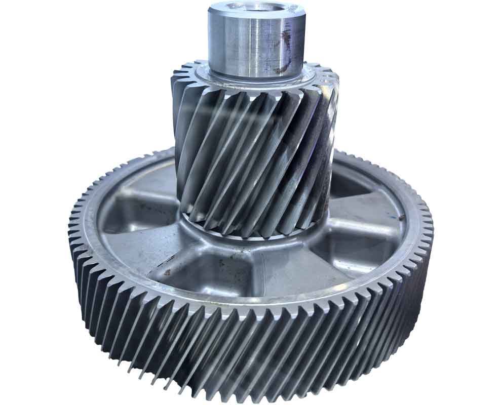
This research establishes a comprehensive reverse design framework for single-degree-of-freedom planetary gear train mechanisms capable of generating complex trajectories essential for automated seedling transplantation. The methodology centers on the monotonicity criterion for determining trajectory reproducibility through reverse gear kinematic analysis.
Transmission Architecture
The mechanism comprises a sun gear (2) fixed to the frame, a planet carrier (1) rotating at constant angular velocity ω₁, coupled intermediate gears (3-4), and a seedling arm (6) rigidly connected to the planetary gear (5). The kinematic relationships governing endpoint position are:
$$ \begin{cases}
x_p = s \cos \phi_1 + l \cos \phi_2 \\
y_p = s \sin \phi_1 + l \sin \phi_2
\end{cases} $$
where \( (x_p, y_p) \) denotes the endpoint coordinates, \( s \) represents the planet carrier length, \( l \) the seedling arm length, \( \phi_1 \) the planet carrier orientation angle, and \( \phi_2 \) the seedling arm relative angle.
Reverse Gear Design Model
Trajectory Definition
Critical trajectory segments are defined using 19 control points \( q_i (i=0,1,…,18) \) with cubic non-uniform B-spline interpolation. The parameterized trajectory \( p(u) \) is expressed through de Boor recursion:
$$ p(u) = \sum_{i=0}^{20} d_i N_{i,3}(u) $$
where \( d_i \) are control vertices and \( N_{i,3}(u) \) cubic basis functions.
Kinematic Inversion
For any trajectory point, the relative angle \( \Delta\phi = \phi_2 – \phi_1 \) is derived through geometric relationships:
$$ \phi_3 = \tan^{-1}\left(\frac{y_p}{x_p}\right) $$
$$ \phi_4 = \cos^{-1}\left(\frac{s^2 + r_p^2 – l^2}{2s r_p}\right) $$
$$ \phi_1 = \begin{cases}
\phi_3 + \phi_4 & \text{(approach)} \\
\phi_3 – \phi_4 & \text{(retraction)}
\end{cases} $$
where \( r_p = \sqrt{x_p^2 + y_p^2} \). The total transmission ratio \( i_{25} \) for the reverse gear system is:
$$ i_{25} = \frac{d\phi_1}{d(\phi_1 + \phi_2)} $$
Transmission Ratio Optimization
The ratio distribution between gear stages minimizes inertial forces:
$$ i_1 = i_{25} \cdot bs, \quad i_2 = i_{25}/i_1 $$
where \( bs \) is the peak-to-valley adjustment coefficient for reverse gear optimization. Table 1 compares transmission characteristics.
| Parameter | Symbol | Value | Unit |
|---|---|---|---|
| Planet carrier length | \( s \) | 173.88 | mm |
| Seedling arm length | \( l \) | 207.81 | mm |
| Maximum transmission ratio | \( i_{max} \) | 1.81 | – |
| Module | \( m \) | 2.53 | mm |
Trajectory Reproducibility Criterion
The critical reverse gear design constraint requires monotonic variation of the relative angle \( \Delta\phi \):
$$ \frac{d(\phi_2 – \phi_1)}{dt} > 0 \quad \forall t \in [0,T] $$
Non-monotonic curves (Fig. 1a) indicate irreproducible trajectories requiring reformulation. This reverse gear criterion identifies feasible kinematic solutions before gear synthesis.
Transmission-Optimized Trajectory Planning
The reverse gear trajectory synthesis follows four principles:
- Position trajectory apex on the maximum radius circle
- Align seedling arm with stem axis at extraction point
- Minimize \( \phi_2 \) at lowest trajectory position
- Position lowest point near theoretical minimum \( N \)
The theoretical minimum position is derived as:
$$ y_{min} = – \sqrt{(s + l)^2 – x_Q^2} $$
where \( (x_Q, y_Q) \) are apex coordinates. Optimized parameters achieve:
$$ \theta_{entry} = 24.3^\circ, \quad \theta_{exit} = 3.6^\circ, \quad \alpha_{tip} = 136.4^\circ $$
Case Implementation
The reverse gear design produced the following performance metrics:
| Performance Indicator | Value | Unit |
|---|---|---|
| Minimum clearance | 21.0 | mm |
| Beak width | 2.07 | mm |
| Planting angle | 76.0 | ° |
| Trajectory height | 285.0 | mm |
| Clearance at discharge | 34.0 | mm |

Comparative Analysis
The reverse gear methodology demonstrates significant improvements over conventional designs:
$$ \Delta W_{min} = -3.88 \text{ mm}, \quad \Delta \theta_{entry} = -2.43^\circ $$
$$ \Delta H_{max} = -42.67 \text{ mm}, \quad \Delta i_{max} = -5.7\% $$
These enhancements reduce gear stress while maintaining trajectory precision essential for seedling integrity during high-speed operation.
Conclusion
The reverse gear design framework establishes: 1) A monotonicity criterion for trajectory feasibility assessment 2) Transmission-optimized trajectory planning rules 3) Practical implementation achieving 21 mm clearance and 1.81 maximum transmission ratio. This methodology enables synthesis of non-circular planetary gear systems for agricultural automation where conventional mechanisms prove inadequate. The reverse gear approach significantly reduces transmission ratio fluctuations while satisfying stringent seedling handling constraints.
