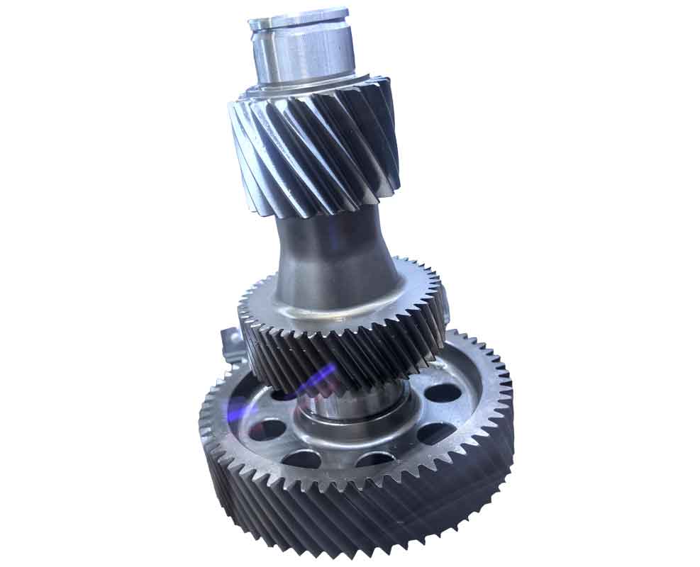
Arc tooth surface gears represent an innovative gear transmission mechanism involving meshing between a helical arc-tooth cylindrical gear and an arc-tooth surface gear. This design significantly enhances load capacity and operational stability in applications like helicopter transmission systems. Reverse gear modeling techniques enable accurate reconstruction of complex tooth geometries from mathematical foundations, facilitating subsequent performance analysis and CNC machining simulations.
Mathematical Foundation of Tooth Surface
The tooth surface geometry is defined within coordinate system $S_i$ fixed to the gear. The axial plane coordinate system (Figure 1) has its horizontal axis aligned with $Z_i$ (gear rotation axis) and vertical axis $r = \sqrt{x_i^2 + y_i^2}$. The origin coincides with the midpoint of the tooth width on $Z_i$. The tooth surface equation is expressed parametrically:
$$
\begin{bmatrix}
x(u, \theta) \\
y(u, \theta) \\
z(u, \theta)
\end{bmatrix}
$$
where $u$ and $\theta$ are surface parameters governing the radial and angular dimensions. Critical design parameters include:
| Parameter | Symbol | Range |
|---|---|---|
| Pressure Angle | $\alpha$ | 20° – 25° |
| Helix Angle | $\beta$ | 25° – 35° |
| Tooth Width | $b$ | 0.2$d_m$ – 0.4$d_m$ |
| Module | $m_n$ | 2 – 8 mm |

Point Cloud Generation via Reverse Gear Methodology
Reverse gear modeling begins with nodal discretization on the axial plane. Nodes are distributed uniformly along tooth length ($Z_i$ direction) and height ($r$ direction), with increased density near the root transition zone. For each node $j$ in the axial plane with coordinates $(z_j’, \sqrt{x_j’^2 + y_j’^2})$:
$$
\begin{cases}
x(u_j, \theta_j)^2 + y(u_j, \theta_j)^2 = x_j’^2 + y_j’^2 \\
z(u_j, \theta_j) = z_j’
\end{cases}
$$
This nonlinear system is solved numerically (using FORTRAN algorithms) for parameters $u_j$ and $\theta_j$, mapping nodes onto the 3D tooth surface. A single tooth requires:
| Region | Nodes Along Length | Nodes Along Height | Total Nodes |
|---|---|---|---|
| Working Surface | 16 | 8 | 128 |
| Root Transition | 16 | 6 | 96 |
| Total per Tooth | 224 |
The point cloud is transformed into tooth space coordinates via rotation by $2\pi/Z_1$ (where $Z_1$ = number of gear teeth) and imported into CATIA for reverse gear surface reconstruction.
Reverse Gear Surface Construction
Working surface reconstruction utilizes multi-section sweeping with precision continuity constraints. Point clouds are sliced along tooth height, generating 8 profile curves. Each curve is defined by 3 control points to minimize complexity while maintaining accuracy. A guide curve along the tooth length (5 control points) ensures curvature continuity. Surface error $\delta$ is constrained by:
$$\delta_{\text{max}} < 0.001 \text{mm}$$
Curvature analysis confirms uniform transitions across all sections (Figure 5). For the non-contact root transition surface, a balance between accuracy and computational efficiency is achieved through bridge surface modeling. This connects the working surface and tooth bottom plane with tangent continuity, accepting slightly higher tolerances:
$$\delta_{\text{transition}} < 0.02 \text{mm}$$
3D Reverse Gear Solid Modeling
The gear blank model (Figure 7) incorporates conical inner/outer surfaces and a planar top surface. Boolean operations create the final geometry:
- Trim and combine working surfaces, transition surfaces, and bottom face into a unified tooth space solid
- Circularly pattern the tooth space around the gear axis ($360^\circ/Z_1$ spacing)
- Subtract patterned tooth spaces from the blank via Boolean subtraction
This reverse gear process yields a precise 3D CAD model (Figure 9) suitable for finite element analysis, motion simulation, and CNC toolpath generation. The reverse gear approach demonstrates significant advantages in handling complex conjugate surfaces inherent to arc tooth gears.
Conclusion
Reverse gear modeling provides a robust framework for developing arc tooth surface gears. By strategically combining high-fidelity surface generation for functional areas with optimized approximations for non-critical zones, it achieves an optimal balance between geometric accuracy and computational efficiency. This methodology establishes the foundation for advanced performance validation and digital manufacturing of these high-performance reverse gear systems. Future work will focus on integrating this reverse gear model with loaded tooth contact analysis and 5-axis CNC machining simulations.
