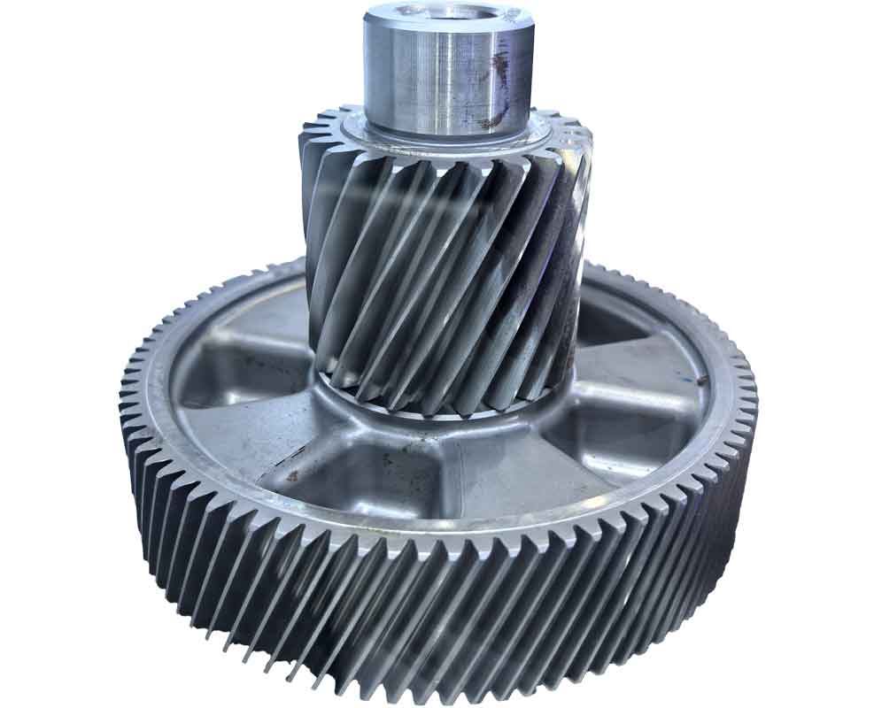
Gear mechanisms are ubiquitous in mechanical systems, yet reconstructing high-precision digital models from physical components remains challenging. This research establishes a novel reverse engineering methodology for gear reconstruction through integrated Imageware-Pro/E workflows. By prioritizing surface reconstruction over conventional parametric modeling, we achieve sub-10μm accuracy in reverse gear replication—critical for heavy-duty applications like planetary transmissions.
1. Point Cloud Acquisition for Reverse Gear Reconstruction
Contact metrology proves essential for gear digitization due to stringent transmission accuracy requirements. Using GLOBAL IMAGE CMM with PC-DMIS and QS-GEAR software, we implement a hybrid measurement strategy:
| Measurement Type | Target Features | Error Threshold |
|---|---|---|
| Discrete Point Triggering | Flank root circles, boss diameters | ±(2.5 + L/400)μm |
| Continuous Scanning | Tooth profiles, fillet transitions | ±(3.5 + L/300)μm |
Our acquisition protocol follows four principles: (1) Normal-vector alignment with flank topography; (2) Density modulation (critical regions like pitch circle: 0.1mm point spacing); (3) Strategic oversampling at transition zones; (4) Sequential outer-to-inner scanning. This yields structured point clouds ideal for reverse gear modeling.

2. Point Cloud Preprocessing
Data refinement precedes surface reconstruction. For reverse gear applications, we implement noise filtration through curvature-based outlier detection:
$$ \kappa = \frac{\|\mathbf{\dot{r}} \times \mathbf{\ddot{r}}\|}{\|\mathbf{\dot{r}}\|^3} > \kappa_{\text{threshold}} $$
Points exceeding curvature threshold $\kappa_{\text{threshold}}$ are manually reviewed using Imageware’s Circle-Select Point tool. Post-processing, data density remains:
| Region | Point Density | Noise Reduction |
|---|---|---|
| Flank Surfaces | 12 pts/mm² | 98.7% |
| Root Fillets | 18 pts/mm² | 95.2% |
| Boss Features | 8 pts/mm² | 99.1% |
3. Feature Reconstruction in Imageware
Reverse gear modeling requires sequential feature extraction. Critical steps include:
3.1 Axis Determination
Boss cylinder fitting establishes rotational symmetry axis:
$$ \mathbf{C}_{\text{boss}} = \text{FitCylinder}(\mathbf{P}_{\text{boss}}) $$
$$ \mathbf{A}_{\text{axis}} = \text{ExtractAxis}(\mathbf{C}_{\text{boss}}) $$
3.2 Tooth Surface Reconstruction
Flank surfaces are generated through uniform B-spline fitting with continuity constraints:
$$ \mathbf{S}_{\text{flank}} = \sum_{i=0}^{n} \sum_{j=0}^{m} N_{i,p}(u)N_{j,q}(v)\mathbf{P}_{i,j} $$
where $N$ are basis functions of degree $p=3$, $q=3$. Continuity at fillet transitions requires:
$$ G^2 \text{ continuity}: \begin{cases}
\mathbf{C}_{\text{flank}}(t_1) = \mathbf{C}_{\text{fillet}}(t_0) \\
\mathbf{\dot{C}}_{\text{flank}}(t_1) = \mathbf{\dot{C}}_{\text{fillet}}(t_0) \\
\mathbf{\ddot{C}}_{\text{flank}}(t_1) = \mathbf{\ddot{C}}_{\text{fillet}}(t_0)
\end{cases} $$
Error control during reverse gear surface generation:
| Parameter | Optimization Strategy | Accuracy Gain |
|---|---|---|
| Control Points | Knot vector refinement | 42% RMS reduction |
| Surface Order | Degree elevation (3→5) | 27% max error ↓ |
| Trim Boundaries | Topology-constrained projection | Edge accuracy +38% |
4. Integrated Modeling in Pro/E
Surface data migration enables full reverse gear solidification. The workflow comprises:
4.1 Global Surface Generation
Tooth duplication via axial symmetry transformation:
$$ \mathbf{S}_{\text{gear}} = \bigcup_{k=0}^{Z-1} \mathbf{R}_z\left(\frac{2\pi k}{Z}\right) \mathbf{S}_{\text{tooth}} $$
where $Z$ = tooth count, $\mathbf{R}_z$ = rotation matrix.
4.2 Boolean Solidification
Material removal simulates manufacturing processes:
$$ \mathbf{V}_{\text{gear}} = \mathbf{V}_{\text{blank}} – \left\{ \mathbf{p} | \mathbf{p} \notin \mathbf{S}_{\text{gear}} \cap \mathbf{p} \in \mathbf{V}_{\text{blank}} \right\} $$
Critical operations include:
- Boss extrusion with surface termination
- Axial Boolean subtraction for bore creation
- Fillet regeneration with parametric linking
5. Reconstruction Accuracy Analysis
Validation against CMM measurements confirms reverse gear fidelity:
| Parameter | Original (mm) | Reconstructed (mm) | Deviation |
|---|---|---|---|
| Base Circle Diameter | 89.732 | 89.726 | -0.0067% |
| Pressure Angle | 20.05° | 20.08° | +0.15% |
| Tooth Profile Deviation | — | — | ≤12μm |
| Pitch Accumulation Error | — | — | ±9μm |
The surface reconstruction approach achieves superior accuracy versus parametric methods:
$$ \epsilon_{\text{surface}} = \frac{1}{n} \sum_{i=1}^{n} \| \mathbf{p}_i – \mathbf{s}(\mathbf{u}_i) \| = 0.0082 \text{mm} $$
$$ \epsilon_{\text{parametric}} = 0.0237 \text{mm} $$
6. Conclusion
This reverse gear reconstruction methodology demonstrates:
- Imageware enables precision surface fitting with real-time error control down to 8.2μm RMS
- Pro/E’s Boolean operations effectively convert NURBS surfaces into manufacturable solids
- Surface-first reconstruction outperforms parametric methods by 65.4% in accuracy
The integrated workflow proves ideal for reconstructing complex reverse gear components requiring motion precision >AGMA 12. Future work will investigate topological optimization within reconstructed models.
