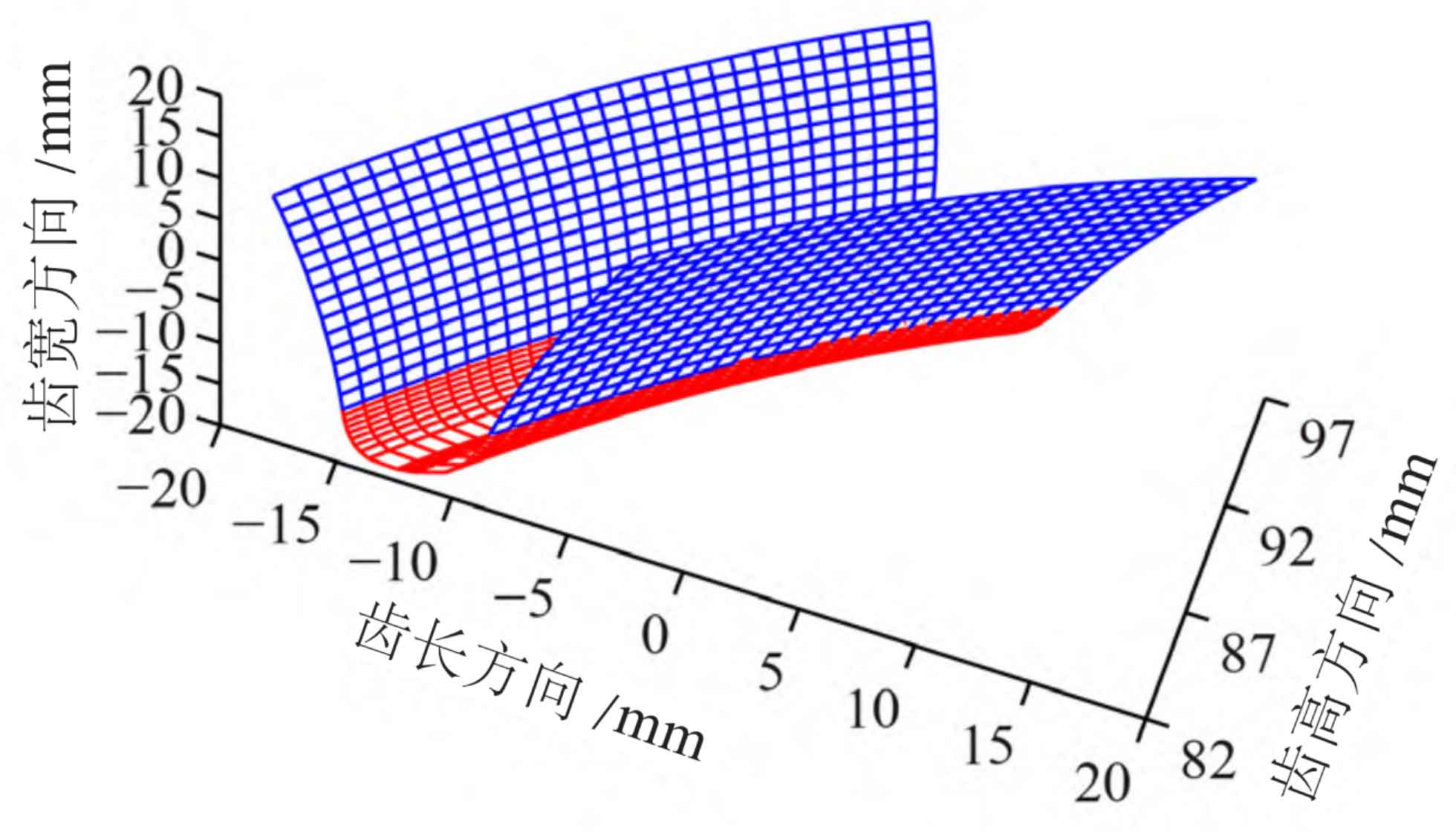
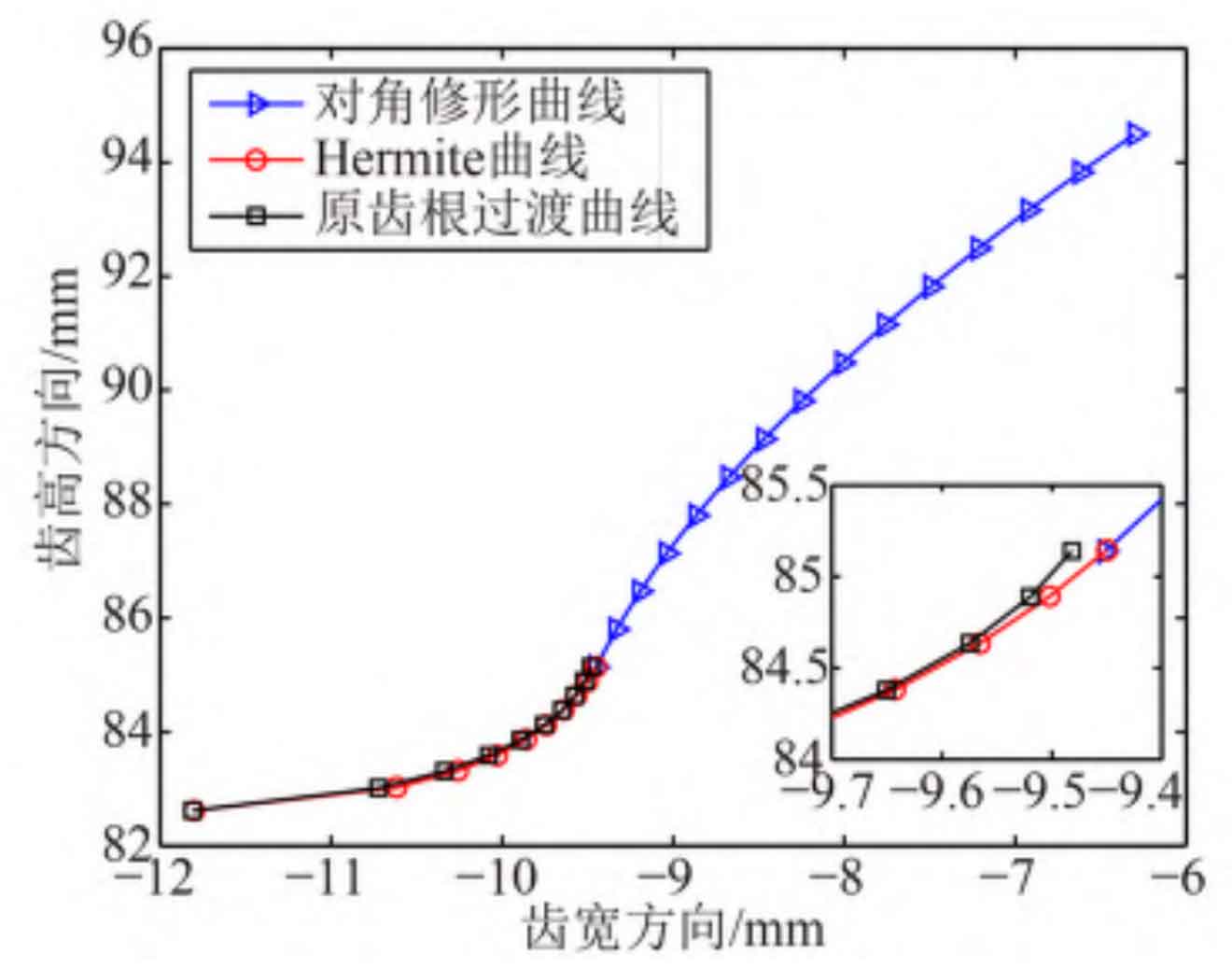
The basic parameters of helical gear pair and diagonal modification are shown in Table 1 and Table 2 respectively. In order to ensure that Hermite surface is close to the original tooth root transition surface, it is found that th=0.9 has the best effect after many adjustments. Digitize and discretize the tooth surface of the quadratic parabola diagonal modified helical gear in the direction of tooth height and tooth width through MATLAB programming, as shown in Figure 1; The curve profile of the right front face of the helical gear after Hermite interpolation is shown in Figure 2.
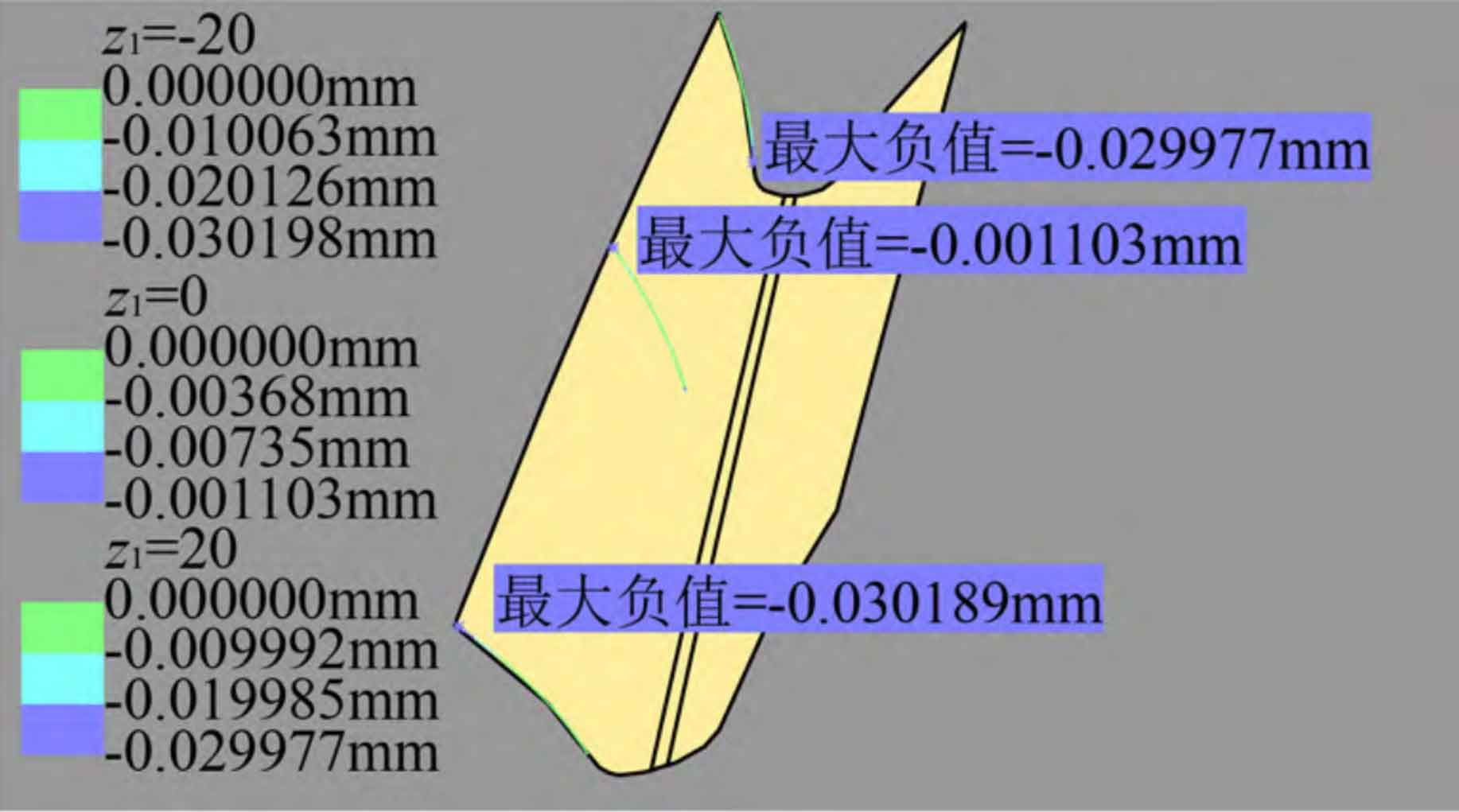
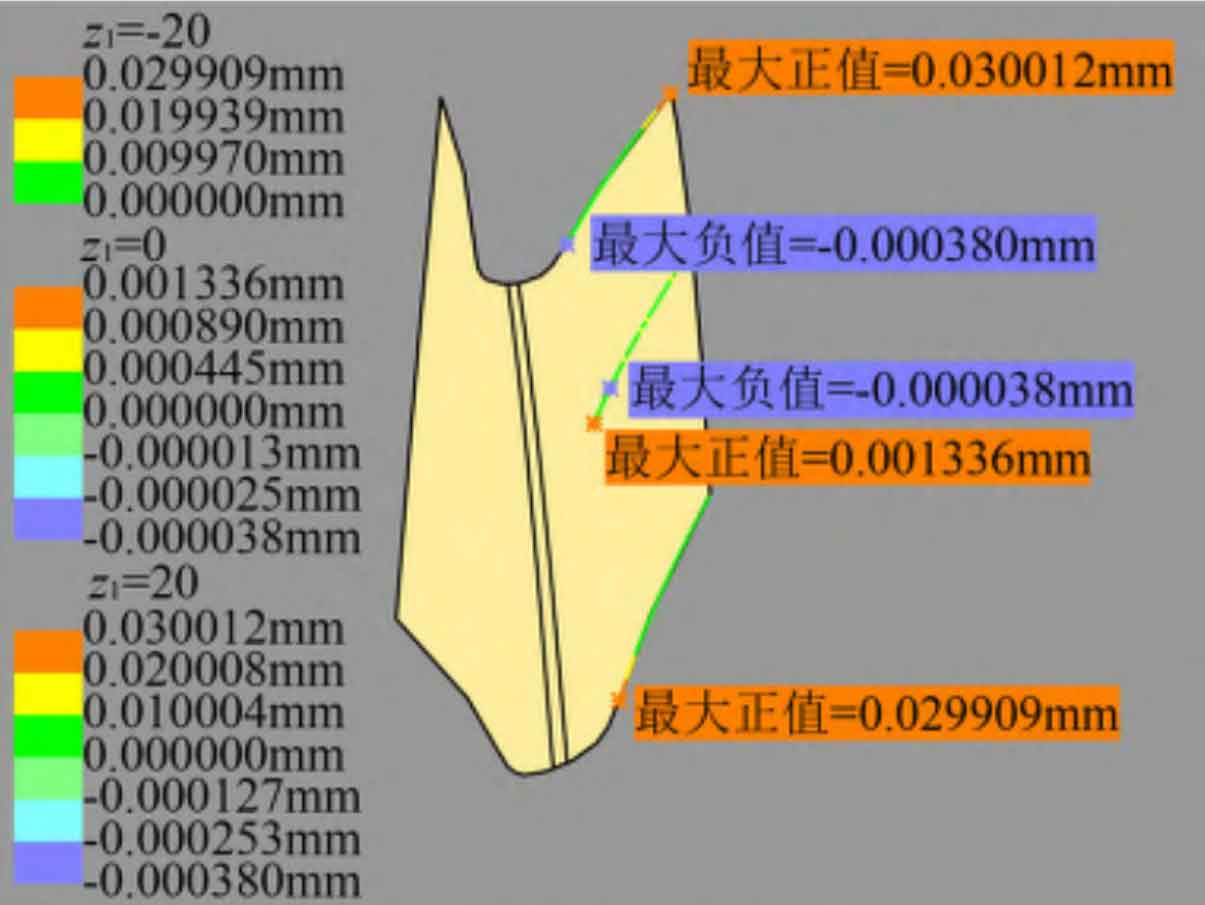
Use the import command of DES module in CATIA to import the discrete coordinate point data of helical gear tooth surface to form a point cloud, and use the power fit command of QSR module to carry out strong fitting to obtain a single tooth groove. The deviation analysis of the modified tooth surface and the standard tooth surface is carried out with the help of the Deviation Analysis command of the DES module. This command defines the normal vector direction of the left tooth surface from the standard tooth surface to the tooth slot, and the normal vector direction of the right tooth surface of the helical gear from the standard tooth surface to the solid. In the direction of tooth profile, select the section of z1 at – 20 mm, 0 mm and 20 mm respectively and import 50 standard tooth surface points each time to calculate the deviation.
| Parameters | pinion | wheel |
| Rotation direction | Dextral rotation | Left-handed |
| Number of teeth | 30 | 72 |
| Modulus/mm | 5.000 | 5.000 |
| Pressure angle/° | 20.000 | 20.000 |
| Helix angle/° | 33.273 | 33.273 |
| Tooth top circle radius/mm | 94.706 | 220.294 |
| Root circle radius/mm | 83.456 | 209.044 |
| Tooth width/mm | 40.000 | 40.000 |
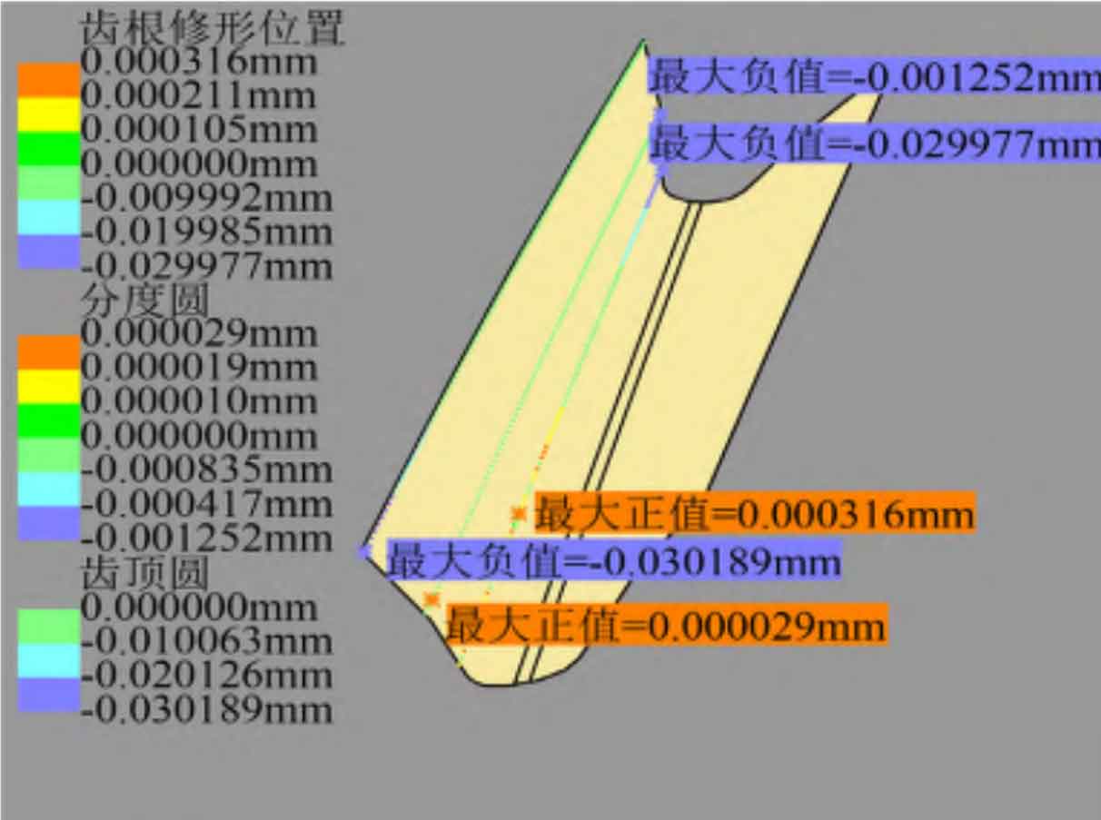
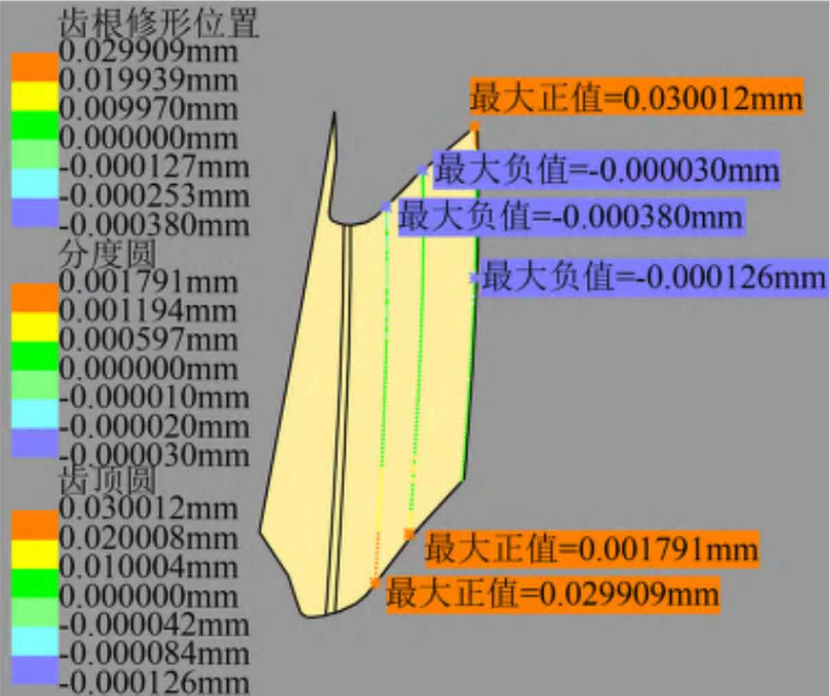
The tooth profile deviation of the left and right tooth surfaces of the helical gear is shown in Figure 3 (a) and (b), and the profile modification amount is 30 for the section deviation when z1 is – 20 mm and 20 mm respectively μ m. The maximum fitting deviation is 0.189 respectively μ m、0.380 μ m; When z1 is 0 mm, the maximum modification amount removed at the end of tooth root modification is 0.7 μ m. The maximum fitting deviation of the tooth root is 0.636 μ m. If the section near the tooth top is not modified, the maximum fitting deviation of this section is 1.103 μ m. Occurs on the left tooth surface. Therefore, the maximum fitting deviation of helical gear tooth profile is 1.103 μ m。 In the direction of tooth direction, select the cross section with radius r of 85.666 mm (the end position of tooth root modification), 89.706 mm (indexing circle) and 94.706 mm (addendum circle) to import 100 standard tooth surface points each time to calculate the deviation. As shown in Fig. 3 (c) and (d), the deviation of the left and right tooth surfaces is 85.666 mm and 94.706 mm respectively, and the amount of modification is 30 μ m. The maximum fitting deviation is 0.380 respectively μ m、0.189 μ m. The section deviation with r of 89.706 mm removes the modification amount 1.1 on the outer end face of the tooth root modification area μ m. However, if this section is close to the tooth top area without modification, the maximum fitting deviation of this section is 0.691 μ m. Occurs on the right tooth surface. Therefore, the maximum fitting deviation of helical gear tooth direction is 0.691 μ m。 To sum up, the maximum fitting deviation of the left and right modified tooth surfaces is about 1.1 μ m。
| Parameters | Addendum | Root |
| Times of shape modification | 2 | 2 |
| Trimming height/mm | 5.000 | 5.000 |
| Modification length/mm | 18.519 | 23.597 |
| Maximum modification amount/μm | 30.000 | 30.000 |
| Helical angle of modification starting line/° | 15.109 | 11.964 |
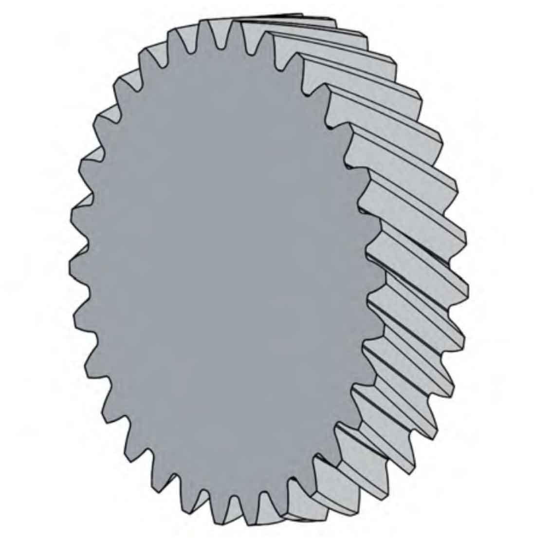
Through the commands of extension, cutting, closing, rotation, array, etc., the 3D model of the quadratic parabola diagonally modified helical gear is obtained, as shown in Figure 4.