
In the modern era of intelligent and digital manufacturing, industrial robotics has become a cornerstone across various sectors of national development. The core of a high-performance robotic joint lies in its drive system, where the rotary vector reducer plays a pivotal role. As a key component signifying a nation’s advanced manufacturing capabilities, the precision and reliability of the rotary vector reducer directly determine the positioning accuracy, load capacity, and operational smoothness of industrial robots. Unlike conventional gearboxes, the rotary vector reducer offers exceptional advantages, making it the ideal solution for applications demanding compact design, high torque, high stiffness, and ultra-precise motion control.
This article delves into the structural intricacies, operational principles, and the critical aspects of transmission accuracy and inherent dynamic characteristics of the rotary vector reducer. From my perspective, analyzing these factors is paramount for advancing its design and application in next-generation precision machinery.
Structural Composition of the Rotary Vector Reducer
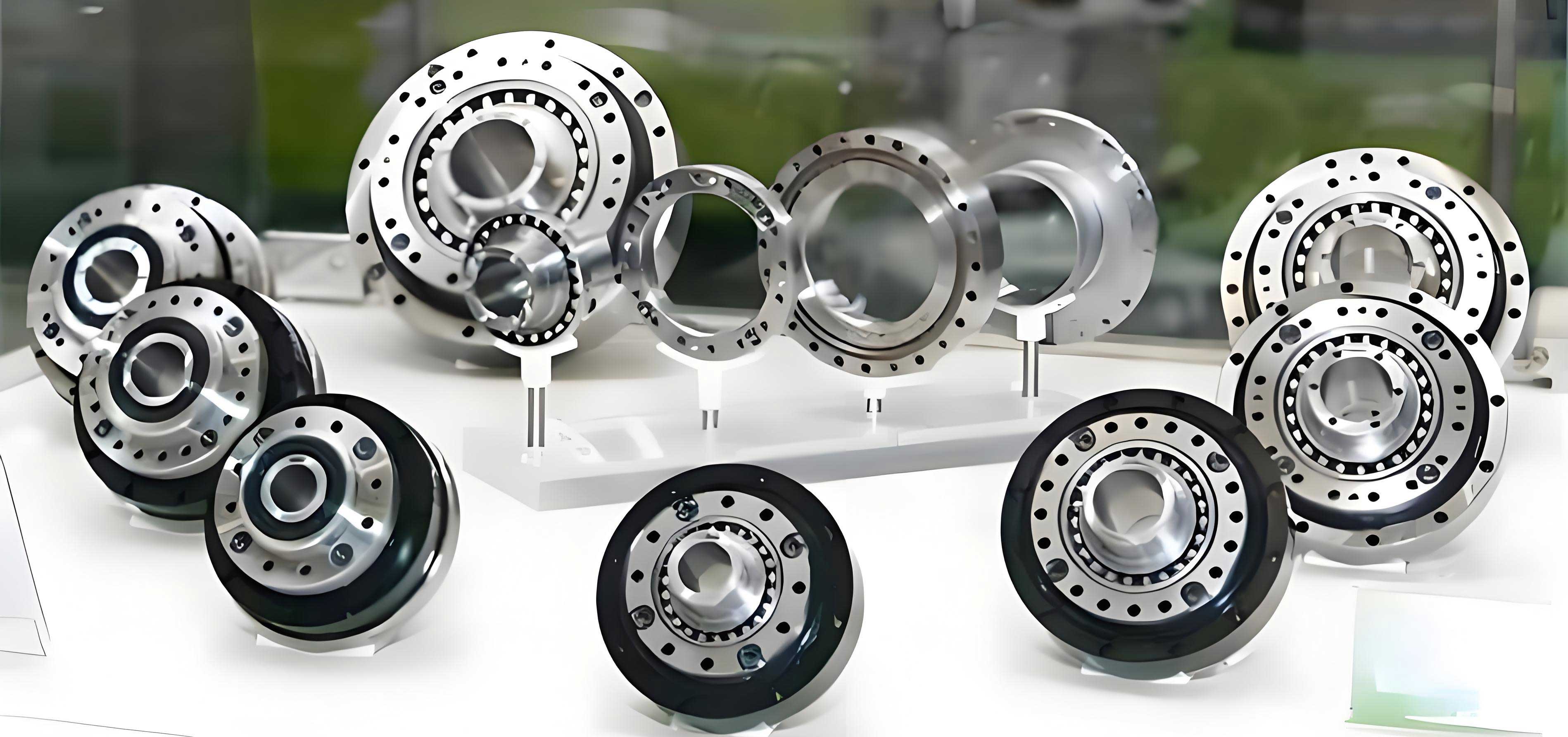
The rotary vector reducer is a sophisticated two-stage speed reduction mechanism. It ingeniously combines a first-stage planetary gear train with a second-stage cycloidal pin-wheel mechanism. This hybrid configuration, forming a closed, statically indeterminate system supported by a central disk, is responsible for its outstanding performance metrics. The compact and robust structure of a typical rotary vector reducer can be visualized in the model below.
The main components of a standard rotary vector reducer are listed and described in the following table:
| Component No. | Name | Function and Description |
|---|---|---|
| 1 | Input Gear Shaft (Sun Gear) | The primary input component. It transmits rotational motion to the first-stage planetary gears. |
| 2 | Planetary Gears | Typically three gears arranged 120° apart. They mesh with the input sun gear, performing the first stage of speed reduction. |
| 3 | Crankshafts (Eccentric Shafts) | Each planetary gear is fixed to a crankshaft via a key. They rotate with the planet gears and their eccentric sections drive the cycloidal discs. |
| 4 | Cycloidal Discs (RV Gears) | Usually two discs arranged 180° out of phase. They undergo eccentric rotation via bearings on the crankshafts and mesh with the stationary pin gear. |
| 5 | Pin Gear (Ring Gear) | A stationary ring with cylindrical pins that internally mesh with the teeth of the cycloidal discs. It is often part of the housing. |
| 6 | Output Disk (Carrier) | Connected to the crankshafts via bearings. It outputs the final reduced speed. In some configurations, it can be fixed to make the housing the output. |
| 7 | Housing | Encloses all components and provides structural support. It often integrates the pin gear and can serve as the output member. |
Transmission Principle and Unique Characteristics
Operating Principle
The transmission process within a rotary vector reducer is a sequential two-stage mechanism:
Stage 1: Planetary Gear Reduction. Power is input through the sun gear (1). This rotation drives the three planetary gears (2), causing them to revolve around the sun gear (first reduction) while also rotating on their own axes. Since each planetary gear is rigidly connected to a crankshaft (3), the crankshafts inherit this compound motion.
Stage 2: Cycloidal Pin-Wheel Reduction. The eccentric portion of each rotating crankshaft imparts an eccentric motion to the cycloidal discs (4). The teeth of the cycloidal discs engage with the stationary pins of the pin gear (5). This engagement forces the cycloidal discs to rotate slowly in the direction opposite to the crankshaft’s spin. This motion is transferred back to the crankshafts, causing them to precess (revolve) around the central axis of the input shaft. Finally, this revolution of the crankshafts is directly transferred to the output disk (6) or carrier, which delivers the final, greatly reduced output speed.
The total reduction ratio \( i_{total} \) of the rotary vector reducer is the product of the ratios of both stages. If \( Z_s \) is the number of teeth on the sun gear, \( Z_p \) is the number of teeth on a planetary gear, \( Z_c \) is the number of lobes on the cycloidal disc, and \( Z_{pin} \) is the number of pins in the ring gear, the ratio can be expressed as:
$$ i_{total} = \left(1 + \frac{Z_s}{Z_p}\right) \times \left(\frac{Z_{pin} – Z_c}{Z_c}\right) $$
The term \( (Z_{pin} – Z_c) \) is typically 1, leading to a very high reduction ratio primarily determined by the first stage and the cycloidal disc’s tooth count \( Z_c \).
Inherent Characteristics and Advantages
The design of the rotary vector reducer confers several superior characteristics, as summarized below:
| Characteristic | Description | Benefit |
|---|---|---|
| High Reduction Ratio & Compactness | Achieves large single-stage ratios (often 30:1 to over 200:1) due to the \( (Z_{pin} – Z_c) \) term. | Enables compact joint design without sacrificing torque output. |
| High Torque Capacity & Rigidity | Utilizes multiple crankshafts and two cycloidal discs with nearly half their teeth in simultaneous contact. | Distributes load, minimizes stress, and provides exceptional torsional stiffness and overload capacity. |
| High Precision & Low Backlash | The multi-tooth meshing of the cycloidal stage and preloaded bearings minimize angular lost motion. | Essential for precise positioning and repeatability in robotics. |
| High Efficiency | Power is transmitted primarily through rolling contact (bearings and cycloid-pin mesh). | Reduces energy loss and heat generation compared to sliding-contact reducers. |
| High Shock Load Resistance | The robust, statically indeterminate structure and large contact area can withstand high momentary loads. | Increases reliability in dynamic start-stop and reversing operations. |
Analysis of Transmission Precision in Rotary Vector Reducers
Transmission error (TE) is the most critical metric for evaluating the precision of a rotary vector reducer. It is defined as the difference between the actual output rotation and the theoretically ideal output rotation for a given input. In robotic joints, minimizing TE is non-negotiable for achieving path accuracy and contouring performance.
Primary Factors Affecting Transmission Precision
From my analysis, the transmission precision of a rotary vector reducer is influenced by a complex interplay of static and dynamic factors:
1. Geometric and Manufacturing Errors: These are foundational errors introduced during component fabrication.
$$ \Delta \theta_{geo} = f(\Delta J_c, \Delta J_p, \Delta e, \Delta r_r, \Delta r_p) $$
Where \( \Delta J_c \) is cycloidal tooth profile error, \( \Delta J_p \) is pin position error, \( \Delta e \) is eccentricity error of the crankshaft, \( \Delta r_r \) is pin radius error, and \( \Delta r_p \) is planetary gear profile error. The machining accuracy of the cycloidal disc and the pin gear directly dictates the base level of achievable precision.
2. Assembly Errors and Clearances (Backlash): Backlash, the lost motion between engaging components, is a major contributor to non-linearity and positioning error. In a rotary vector reducer, backlash arises from:
- Clearance between cycloidal teeth and pins (\( \delta_{cp} \)).
- Clearance in the bearings supporting the crankshafts and output disk (\( \delta_b \)).
- Fit clearances between components like the crankshaft and planetary gear (\( \delta_f \)).
The total equivalent angular backlash \( \phi_{bl} \) can be modeled as a function of these individual clearances referenced to the output shaft.
3. Load-Induced Deformations: Under operational torque, all components experience elastic deformation (torsion, bending, contact compression). This elastic deformation \( \Delta \theta_{elastic} \) is a function of the applied torque \( T \) and the system’s torsional stiffness \( K_t \).
$$ \Delta \theta_{elastic} \approx \frac{T}{K_t} $$
A higher system stiffness minimizes this error. The unique double-supported structure of the rotary vector reducer inherently provides high stiffness.
4. Thermal Effects: Temperature changes during operation cause thermal expansion of metals, altering clearances and preloads. This can either increase backlash or induce binding, both degrading precision.
Modeling and Control of Transmission Error
A comprehensive model for the total transmission error \( \Delta \theta_{total} \) of a rotary vector reducer must integrate these factors:
$$ \Delta \theta_{total}(t, T, \theta_{in}) = \Delta \theta_{geo} + \Delta \theta_{bl}(T, \theta_{in}) + \Delta \theta_{elastic}(T) + \Delta \theta_{thermal}(\Delta T) + \Delta \theta_{dynamic}(t) $$
Where \( \Delta \theta_{dynamic} \) represents errors from vibrations and dynamic excitations.
To achieve the ultra-high precision required for robotics, manufacturers implement several control strategies:
| Strategy | Method | Impact on Precision |
|---|---|---|
| Precision Manufacturing | Ultra-precise grinding of cycloidal profiles, honing of pin holes, and high-grade bearing manufacturing. | Minimizes \( \Delta \theta_{geo} \), the fundamental error floor. |
| Backlash Elimination | Using tapered pins, adjustable preload mechanisms, or elastic deformation preload in the pin circle. | Actively reduces \( \delta_{cp} \), often achieving near-zero backlash conditions. |
| Stiffness Optimization | Optimizing crankshaft diameter, bearing selection, and housing wall thickness using FEA. | Maximizes \( K_t \), minimizing \( \Delta \theta_{elastic} \). |
| Thermal Management | Using materials with matched thermal expansion coefficients, advanced lubricants, and sometimes cooling. | Stabilizes performance by reducing \( \Delta \theta_{thermal} \). |
| Error Compensation | Mapping the reducer’s error characteristic and compensating for it in the robot’s controller software. | Corrects for the residual systematic error \( \Delta \theta_{total} \). |
Inherent Dynamic Characteristics and Modal Analysis
Beyond static precision, the dynamic behavior or inherent characteristics of the rotary vector reducer are crucial for high-speed, high-acceleration applications. These characteristics determine its response to dynamic loads, vibration levels, and noise generation.
Torsional Vibration and Natural Frequencies
The rotary vector reducer is a complex multi-inertia, multi-stiffness torsional system. A simplified 3-DOF model can represent the primary inertial elements:
- Input shaft and sun gear inertia: \( J_{in} \)
- Planetary gear and crankshaft inertia (reflected): \( J_{cr} \)
- Output disk and load inertia: \( J_{out} \)
These are connected by torsional stiffnesses \( K_1 \) (first-stage mesh stiffness) and \( K_2 \) (second-stage effective torsional stiffness). The equations of motion for free vibration can be derived as:
$$ J_{in}\ddot{\theta}_{in} + K_1(\theta_{in} – \theta_{cr}/i_1) = 0 $$
$$ J_{cr}\ddot{\theta}_{cr} + K_1(\theta_{cr}/i_1 – \theta_{in})/i_1 + K_2(\theta_{cr} – \theta_{out}/i_2) = 0 $$
$$ J_{out}\ddot{\theta}_{out} + K_2(\theta_{out}/i_2 – \theta_{cr})/i_2 = 0 $$
Where \( i_1 \) and \( i_2 \) are the speed ratios of the respective stages. Solving the eigenvalue problem for this system yields the natural frequencies \( \omega_n \). Excitation at these frequencies, particularly from time-varying mesh stiffness \( K_1(t) \) and \( K_2(t) \), can lead to resonance and increased vibration/noise.
Vibration Sources and Mitigation
The main sources of dynamic excitation within a rotary vector reducer include:
- Time-Varying Mesh Stiffness (TVMS): As gears and cycloid teeth engage and disengage, the effective mesh stiffness fluctuates periodically, acting as a parametric exciter.
- Transmission Error (TE) Excitation: The static transmission error \( \Delta \theta_{total} \) itself, when varying with rotational position, acts as a displacement excitation forcing function.
- Eccentric Mass Unbalance: The rotating eccentric masses of the crankshafts and cycloidal discs, if not perfectly balanced, cause synchronous vibration.
The dual-cycloid-disc design, phased 180° apart, is itself a powerful mitigation strategy. It cancels out the primary radial forces generated by the eccentric motion, significantly reducing vibration and allowing for smoother operation at high speeds. Furthermore, optimizing the cycloid tooth profile to ensure more teeth are in contact simultaneously helps to reduce the amplitude of TVMS fluctuations.
Conclusion and Perspective
The rotary vector reducer stands as a masterpiece of precision mechanical design, seamlessly integrating planetary and cycloidal principles to achieve unparalleled performance in a compact package. Its high torque density, exceptional rigidity, and potential for high precision make it indispensable for advanced robotics and automation. However, realizing its full potential requires a deep, integrated understanding of its structure, the multifaceted factors governing its transmission precision, and its inherent dynamic characteristics.
From my viewpoint, future advancements in rotary vector reducer technology will focus on several key areas: the development of novel, optimized cycloidal tooth profiles that further minimize transmission error and vibration; the application of advanced materials and coatings to reduce wear and thermal distortion; the integration of sensor systems for real-time health monitoring and error compensation; and the refinement of system-level dynamic models that accurately predict behavior under complex multi-axis loading conditions. As the demand for faster, more precise, and more reliable robots grows, the continuous innovation in rotary vector reducer design and manufacturing will remain a critical enabler for the next generation of industrial automation.