
I have long been interested in the way friction, wear, and lubrication interact inside mechanical transmissions. When I examine a screw gear drive, I see a compact and powerful mechanism that can transmit motion between non-intersecting axes, usually at a right angle. The screw gear drive, also called a worm gear drive, is widely used because it offers a large reduction ratio, smooth operation, low noise, and a self-locking ability under certain conditions. However, I also recognize its weaknesses: high sliding velocity, severe heat generation, and a strong tendency toward scuffing and wear. These weaknesses make the lubrication of a screw gear drive far more critical than that of many other gear systems. My work therefore focuses on a magnetic fluid lubrication strategy for a screw gear drive. I designed a magnetic circuit, simulated its field distribution, built a test rig, and measured temperature rise and wear under several operating conditions. The results suggest that magnetic fluid lubrication can reduce thermal load and improve the anti-wear behavior of a screw gear drive, especially when the magnetic field is properly matched to the operating condition.
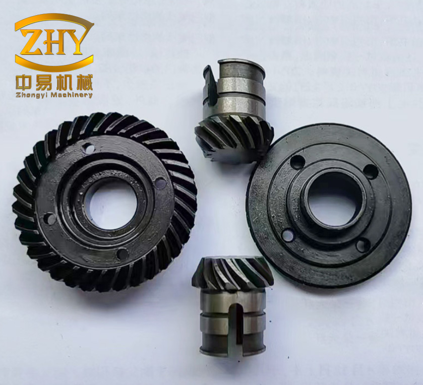
I begin with a simple statement of the problem. In any screw gear drive, the teeth of the worm and the wheel slide against each other with a relative velocity that is much larger than the rolling velocity found in parallel-axis gears. The contact is a line contact that becomes a complex ellipse-like region under load. Because the sliding speed is high and the contact area is narrow, the oil film is easily disrupted. If the lubricant cannot remain in the contact zone, metal-to-metal contact becomes frequent, and the local temperature can rise quickly. This temperature rise reduces viscosity, weakens the film, and accelerates wear. In extreme cases, the screw gear drive fails by scuffing, pitting, or severe adhesive wear. I therefore see lubrication as the central design challenge for a reliable screw gear drive.
To make my reasoning precise, I use several basic relations. The transmission ratio of a screw gear drive can be written as
$$i = \frac{n_1}{n_2} = \frac{z_2}{z_1}$$
where \(n_1\) is the input speed, \(n_2\) is the output speed, \(z_1\) is the number of starts on the screw, and \(z_2\) is the number of teeth on the wheel. The sliding velocity at the mesh is approximately
$$v_s = \frac{v_1}{\cos \gamma}$$
where \(v_1\) is the pitch-line velocity of the screw and \(\gamma\) is the lead angle. This equation shows directly why a screw gear drive generates more heat than a spur gear pair: the sliding component is not a small correction; it is the dominant motion. The friction power loss can be estimated as
$$P_f = \mu_f F_n v_s$$
where \(\mu_f\) is the friction coefficient, \(F_n\) is the normal force, and \(v_s\) is the sliding velocity. Because \(v_s\) is large, even a moderate friction coefficient produces significant heating. This is why I focus on a lubricant that can be held in the mesh by an external magnetic field. If the lubricant remains in the contact region, the friction coefficient and the wear rate can both be reduced.
Before I discuss magnetic fluids, I should summarize the main features of a screw gear drive in a compact table. This helps me compare the advantages and disadvantages that drive my design decisions.
| Feature | Description | Consequence for Lubrication |
|---|---|---|
| Transmission ratio | Large ratio possible with a single stage | Compact layout, but high sliding speed |
| Motion | Smooth and quiet because of continuous contact | Good for precision, but heat is continuous |
| Self-locking | Occurs when lead angle is below the equivalent friction angle | Useful for holding loads, but friction is high |
| Contact type | Line contact that becomes elliptical under load | Oil film is difficult to maintain |
| Failure modes | Scuffing, pitting, wear, and tooth breakage | Lubricant must resist high temperature and high shear |
| Efficiency | Lower than many gear types | More energy becomes heat |
I have found that the failure modes of a screw gear drive are closely connected to its lubrication state. When the lubricant film is thin or broken, the wheel tooth surface suffers adhesive wear. When the load is high and the speed is high, scuffing can appear as deep, wide furrows. When the load is moderate but repeated many times, pitting can appear near the pitch line. In all these cases, the root cause is the same: the lubricant cannot stay in the contact zone, and the local thermal and mechanical stresses exceed the capability of the material. Therefore, a useful lubrication design for a screw gear drive must do more than simply supply oil; it must keep the oil where it is needed.
Conventional lubricants for a screw gear drive include compounded mineral oils, extreme-pressure worm gear oils, and synthetic polyglycol oils. Each has merits. Compounded oils reduce friction and help prevent overheating. Extreme-pressure oils improve load capacity but may contain additives that attack copper alloys. Synthetic oils offer a wide temperature range and long service life, but they are more expensive. I respect these developments, but I want to explore a different route. A magnetic fluid is a stable colloidal suspension of magnetic nanoparticles in a carrier liquid. It behaves as a liquid, yet it responds to a magnetic field. This dual nature makes it attractive for a screw gear drive, because I can use a magnetic circuit to localize the lubricant in the mesh. In my view, the key phrase for this application is not merely lubrication, but localized lubrication of a screw gear drive.
The physical properties of a magnetic fluid are central to my design. I consider four properties especially important: magnetization, viscosity, thermal behavior, and stability. The magnetization of a magnetic fluid can be described by a Langevin-type relation:
$$M = M_s \left( \coth \alpha – \frac{1}{\alpha} \right)$$
where \(M_s\) is the saturation magnetization and \(\alpha\) is given by
$$\alpha = \frac{\mu_0 m H}{k_B T}$$
Here \(\mu_0\) is the vacuum permeability, \(m\) is the magnetic moment of a particle, \(H\) is the magnetic field strength, \(k_B\) is Boltzmann’s constant, and \(T\) is the absolute temperature. This equation tells me that at low field the magnetization increases almost linearly, while at high field it approaches saturation. For a screw gear drive, this means that increasing the external field can increase the magnetic force on the fluid, but only up to a limit. Once the fluid is saturated, a stronger field does not increase its magnetization further. Instead, it may increase viscous dissipation and magnetic drag. This is one reason why my experiments show an optimum field rather than a monotonic improvement.
The viscosity of a magnetic fluid also changes with the magnetic field. A simplified expression for the field-dependent viscosity is
$$\eta = \eta_0 \left( 1 + \frac{3}{2} \phi \frac{\alpha – \tanh \alpha}{\alpha + \tanh \alpha} \right)$$
where \(\eta_0\) is the viscosity without field and \(\phi\) is the volume fraction of magnetic particles. This relation is not exact for all magnetic fluids, but it captures the essential trend: a stronger field increases the apparent viscosity. A higher viscosity can improve load capacity, but it also increases churning loss and heat generation. In a screw gear drive, the churning loss is already significant because the lubricant is thrown by the rotating screw. Therefore, I must balance the benefit of higher load capacity against the penalty of higher viscous heating.
I also note that a magnetic fluid is superparamagnetic. In the absence of a field, the magnetic nanoparticles are randomly oriented because of Brownian motion. When a field is applied, the particles align with the field. This alignment can create a chain-like microstructure. The particles can act like tiny rollers between the surfaces, and the aligned structure can increase the effective film thickness. These effects are beneficial for a screw gear drive, because they can reduce asperity contact and delay scuffing. At the same time, the particles must remain stable. If they agglomerate, they can form large clusters that scratch the surface instead of protecting it. For this reason, I selected a well-dispersed magnetic fluid with a narrow particle-size distribution and a suitable surfactant.
My magnetic circuit design begins with the basic laws of magnetic circuits. These laws are analogous to electrical circuit laws, and I often use this analogy to organize my calculations. The magnetomotive force is
$$F = N I$$
where \(N\) is the number of turns and \(I\) is the current. In a permanent-magnet circuit, the magnet itself provides the magnetomotive force. The magnetic flux is
$$\Phi = B S$$
where \(B\) is the magnetic flux density and \(S\) is the cross-sectional area. The reluctance of a magnetic path is
$$R_m = \frac{l}{\mu S}$$
where \(l\) is the path length and \(\mu\) is the permeability. The magnetic Ohm law is then
$$\Phi = \frac{F}{R_m}$$
The Kirchhoff laws for magnetic circuits are
$$\sum_i \Phi_i = 0$$
for a node, and
$$\sum_i H_i l_i = \sum_j N_j I_j$$
for a closed loop. These equations allow me to estimate the field in the air gap and in the teeth of the screw gear drive. Of course, because the geometry is complex and the materials are nonlinear, I use finite-element analysis for accurate results.
The analogy between electric and magnetic circuits is useful enough that I present it in a table. This table helps me explain the design to others and also helps me check the units and the logic of my model.
| Electrical Quantity | Magnetic Quantity | Symbol | Unit |
|---|---|---|---|
| Current | Magnetic flux | \(\Phi\) | Wb |
| Voltage | Magnetomotive force | \(F\) | A |
| Conductance | Permeance | \(\Lambda\) | H |
| Resistance | Reluctance | \(R_m\) | A/Wb |
| Current density | Magnetic flux density | \(B\) | T |
| Electric field | Magnetic field strength | \(H\) | A/m |
I designed two candidate magnetic circuits for the screw gear drive. The first used radially magnetized arc magnets placed near the screw. A T-shaped support held the magnets and a magnetic conductive shoe. The magnets faced each other with opposite polarity, and a small air gap separated the magnet assembly from the screw. This design could produce a field on the screw, but the field decayed rapidly with distance. When I simulated the field, I found that the flux density in the actual mesh region was weak. The structure also occupied valuable space inside the reducer housing. I did not consider this a good solution for a screw gear drive, because the mesh region is where the lubricant must be held.
The second design used a closed magnetic loop. I modified the bearing covers of the screw and the wheel. A cylindrical permanent magnet was inserted into each cover. A magnetic conductive strip connected the two magnets outside the housing. The screw, the wheel, and the meshing teeth formed part of the loop. The magnet in the screw cover was oriented axially, and the magnet in the wheel cover was also oriented axially, but in the opposite direction. This arrangement produced a closed path: from the screw magnet, through the screw shaft, through the screw teeth, across the mesh, through the wheel teeth, through the wheel, through the wheel magnet, and back through the conductive strip. Because the loop was closed, the magnetic flux was concentrated in the mesh rather than being lost to the surrounding air. This is the design I selected for my screw gear drive experiments.
I used finite-element software to simulate the magnetic field. My simulation workflow included selecting a three-dimensional direct-current magnetic solver, importing the geometry, assigning materials, setting the permanent magnet orientation, meshing the model, solving the nonlinear field equations, and post-processing the flux density. I paid special attention to the mesh in the tooth contact region, because the field gradient is high there. I also defined a path through the middle plane of the mesh so that I could compare the flux density along the contact line.
The materials I considered are listed in the following table. The screw and wheel can be made of different steels or cast iron. The magnetic properties of the screw gear drive components influence the field distribution, so I did not treat the material choice as independent of the magnetic circuit. In general, a material with higher permeability can carry more flux, but it can also saturate. I therefore included the nonlinear B-H curve of 45 steel and the default cast-iron curve in my model.
| Component | Material | Relative Permeability | Role in Magnetic Circuit |
|---|---|---|---|
| Screw | 45 steel | Nonlinear | Flux path and load-carrying member |
| Wheel | Cast iron or 45 steel | Nonlinear | Flux path and wear surface |
| Permanent magnet | NdFeB | ~1.05 | Field source |
| Conductive strip | Soft iron | 4000 | Return path |
| Housing | Aluminum or nonmagnetic steel | ~1 | Structural support, magnetic isolation |
| Air gap | Air | 1 | High reluctance region |
The simulation results showed a clear difference between the two designs. In the open design, the flux density near the magnet was high, but it fell to a low value before reaching the mesh. In the closed design, the flux density in the mesh was much higher, and the region of high flux density was concentrated around the contacting teeth. I also found that the flux density in the mesh increased almost linearly with the remanence of the permanent magnet. This gave me a practical way to control the field in the screw gear drive: I could select permanent magnets with different surface flux densities or demagnetize them to intermediate levels.
I also studied the effect of the wheel material. When the wheel was made of cast iron and the screw was made of 45 steel, the field in the mesh was slightly lower than when both were made of 45 steel. The difference was not large, but it was noticeable. The reason is that the magnetization curve of cast iron is lower than that of 45 steel at high field. For a screw gear drive, this means that the material choice should consider both mechanical performance and magnetic performance. If the load is moderate and the magnetic circuit is strong, a cast-iron wheel can be acceptable. If the load is high and the field must be concentrated, a steel wheel is preferable. Of course, the final choice must also consider cost, machinability, and wear resistance.
To verify the magnetic circuit, I built a transparent model of the screw gear drive using acrylic plates. I filled the mesh region with a small amount of magnetic fluid and observed its behavior with and without the magnetic field. Without the field, the fluid was thrown away as the screw rotated. With the field, the fluid remained attached to the teeth and formed a dense bridge across the mesh. At low speed, the magnetic fluid stayed in the contact zone even when the screw rotated. At higher speed, the fluid without the field splashed outward, while the fluid with the field remained coherent for a longer time. This observation confirmed that the closed magnetic circuit could localize the lubricant in the mesh of a screw gear drive.
After validating the magnetic circuit, I designed and built a screw gear drive test rig. I chose an open power-flow configuration because it is simple, flexible, and easy to instrument. The rig consists of a drive module, a screw gear reducer, a loading module, a temperature measurement module, and a data acquisition system. The drive module is a stepper motor. The loading module is a magnetic particle brake. The temperature sensor is an infrared module that measures the surface temperature of the screw shaft without contact. The data are recorded on a computer. This arrangement allows me to change speed and load independently and to measure the thermal response of the screw gear drive.
The speed of the stepper motor is controlled by the pulse frequency. The relation between the input frequency and the motor speed is
$$n = \frac{60 f}{200 x}$$
where \(f\) is the pulse frequency in hertz, \(x\) is the microstep setting, and \(n\) is the motor speed in revolutions per minute. This equation is important for my experiments because it allows me to set the input speed of the screw gear drive precisely. The magnetic particle brake provides a controllable load torque. Its torque is approximately proportional to the excitation current, so I can adjust the load by turning a control knob. The brake torque is nearly constant over a range of speeds, which is convenient for comparative tests.
The main components of my test rig are summarized in the following table. I selected each component to match the size and power level of the screw gear drive. The reducer has a center distance of 40 mm, a single-start screw, and a wheel with 30 teeth. The maximum input speed in my tests was 900 rpm, and the maximum load torque was 7.5 N·m. These values are high enough to produce measurable heating and wear, yet low enough to avoid immediate failure of the screw gear drive.
| Module | Component | Specification | Function |
|---|---|---|---|
| Drive | Stepper motor | 2.2 N·m, 1000 rpm rated | Provides controlled input speed |
| Drive | Microstep driver | DC 16–70 V, 800–51200 steps/rev | Controls motor speed and direction |
| Drive | Pulse generator | Adjustable frequency and duty cycle | Generates step pulses |
| Load | Magnetic particle brake | 50 N·m rated torque | Applies load torque to the screw gear drive |
| Load | Manual tension controller | 24 V input, adjustable output | Sets brake current and torque |
| Measurement | Infrared temperature sensor | −50 to 320 °C, ±0.5 °C near room temperature | Measures screw shaft surface temperature |
| Transmission | Screw gear reducer | 40 mm center distance, \(z_1=1\), \(z_2=30\) | Tested screw gear drive |
| Coupling | Flexible couplings | Compensates small misalignment | Connects motor, reducer, and brake |
For the lubrication experiments, I used a diester carrier liquid and two diester-based magnetic fluids. The magnetic fluids contained Fe₃O₄ nanoparticles with an average diameter of about 10 nm. The saturation magnetization was either 200 Gs or 440 Gs. The carrier liquid had no magnetic particles. I applied the same volume of lubricant, 0.1 ml, in each test. Before assembly, I cleaned the screw gear drive components in an ultrasonic bath and dried them. After assembly, I mounted the reducer on the test rig, added the lubricant, and started the test. I recorded the screw shaft surface temperature until it reached a steady value. After the test, I disassembled the reducer, cleaned the wheel teeth, and examined the wear surfaces with an optical microscope and a three-dimensional profilometer.
The lubricant parameters are listed in the following table. The table shows that the magnetic fluids have higher density and higher saturation magnetization than the carrier liquid. The particle volume fraction also increases with saturation magnetization. These differences matter because a higher particle fraction can increase viscosity and load capacity, but it can also increase viscous heating. The experiments were designed to separate these effects as much as possible.
| Lubricant | Fe₃O₄ Content | Particle Size | Density | Saturation Magnetization |
|---|---|---|---|---|
| Diester carrier | 0 | — | 0.969 g/cm³ | 0 |
| Magnetic fluid A | 21% | 10 nm | 1.10 g/cm³ | 200 Gs |
| Magnetic fluid B | 53% | 10 nm | 1.33 g/cm³ | 440 Gs |
I designed the experiments around four variables: input speed, load torque, external magnetic field strength, and saturation magnetization of the magnetic fluid. For the speed tests, I used 300 rpm, 600 rpm, and 900 rpm at a constant load torque of 5.0 N·m. For the load tests, I used 2.5 N·m, 5.0 N·m, and 7.5 N·m at a constant input speed of 600 rpm. For the field tests, I used permanent magnets with surface flux densities of 150 mT, 250 mT, and 350 mT. For the saturation magnetization tests, I compared magnetic fluid A and magnetic fluid B under low-speed high-load and high-speed high-load conditions. In every case, I compared the magnetic fluid with the diester carrier to isolate the effect of the magnetic particles and the external field.
The temperature results for different input speeds are summarized in the following table. The values are the steady-state surface temperatures of the screw shaft. I define the temperature reduction as
$$\Delta T = T_{\text{carrier}} – T_{\text{magnetic}}$$
and the percentage reduction as
$$\eta_T = \frac{\Delta T}{T_{\text{carrier}}} \times 100\%$$
These definitions help me compare the thermal benefit of magnetic fluid lubrication across different screw gear drive operating conditions. The table shows that at 300 rpm the difference between the carrier liquid and the magnetic fluid is small. At 600 rpm and 900 rpm, the difference becomes much larger. The maximum reduction in my speed tests was about 17.1%. This is a significant improvement for a screw gear drive, because a lower steady-state temperature means lower thermal expansion, slower lubricant degradation, and a longer service life.
| Input Speed (rpm) | Load Torque (N·m) | Carrier Temperature (°C) | Magnetic Fluid Temperature (°C) | Reduction (%) |
|---|---|---|---|---|
| 300 | 5.0 | 35.0 | 34.0 | 2.9 |
| 600 | 5.0 | 44.0 | 36.0 | 18.2 |
| 900 | 5.0 | 48.0 | 40.0 | 16.7 |
In addition to temperature, I examined the wear scars on the wheel teeth. After the speed tests, I found that the carrier liquid produced progressively deeper and wider wear tracks as the speed increased. The tracks changed from shallow scratches to deeper furrows. In contrast, the magnetic fluid produced wear tracks that changed less with speed. The depth of the wear scar remained relatively small even at 900 rpm. This suggests that the magnetic fluid formed a more stable film in the mesh of the screw gear drive, and that the film was less sensitive to the sliding speed. The magnetic particles may have acted as micro-rollers and may also have increased the effective viscosity in the contact zone. Both effects are beneficial for a screw gear drive operating at high speed.
The load tests produced a similar but not identical trend. The following table gives the steady-state temperatures for different load torques at 600 rpm. The carrier liquid showed a large increase in temperature as the load increased from 2.5 N·m to 7.5 N·m. The magnetic fluid showed a smaller increase. At 2.5 N·m, the magnetic fluid temperature was about 34 °C, while the carrier was about 36 °C. At 5.0 N·m, the magnetic fluid remained near 34–36 °C, while the carrier rose to 42 °C. At 7.5 N·m, both temperatures rose, but the magnetic fluid was still lower. The wear observations showed that the carrier liquid produced severe scuffing at 7.5 N·m, with block-like pits and loose debris. The magnetic fluid produced smoother surfaces with shallower scratches. This indicates that magnetic fluid lubrication can improve the anti-scuffing ability of a screw gear drive under high load.
| Load Torque (N·m) | Input Speed (rpm) | Carrier Temperature (°C) | Magnetic Fluid Temperature (°C) | Reduction (%) |
|---|---|---|---|---|
| 2.5 | 600 | 36.0 | 34.0 | 5.6 |
| 5.0 | 600 | 42.0 | 35.0 | 16.7 |
| 7.5 | 600 | 54.0 | 45.0 | 16.7 |
The external magnetic field strength also had a strong effect. I used three permanent magnets with different surface flux densities. The magnetic field in the mesh increased with the magnet strength. The following table shows the steady-state temperatures for three operating conditions: low speed and light load, medium speed and medium load, and high speed and heavy load. For the low-speed light-load condition, the temperature was almost independent of the field, because the heat generation was small and even a weak field was enough to hold the magnetic fluid in the mesh. For the medium condition, the temperature decreased as the field increased from 150 mT to 250 mT, and then increased slightly at 350 mT. For the high-speed heavy-load condition, the temperature was high for all field strengths, and the benefit of the field was reduced. This means that the magnetic field must be matched to the operating condition of the screw gear drive. A stronger field is not always better.
| Condition | Speed (rpm) | Load (N·m) | 150 mT (°C) | 250 mT (°C) | 350 mT (°C) |
|---|---|---|---|---|---|
| Low speed, light load | 300 | 2.5 | 31.0 | 31.0 | 31.0 |
| Medium speed, medium load | 600 | 5.0 | 39.0 | 35.0 | 37.0 |
| High speed, heavy load | 600 | 7.5 | 46.0 | 44.0 | 45.0 |
I also measured the wear depth under different field strengths. The wear depth is not simply a monotonic function of the field. In my tests, the wear depth was smallest at an intermediate field strength. At 150 mT, the magnetic force was weak, so some lubricant escaped from the mesh. At 350 mT, the magnetic force was strong, but the magnetic particles were pulled together more tightly, and the viscous drag increased. The increased drag can raise the temperature and reduce the film thickness. Therefore, there is an optimum field for a given screw gear drive and a given operating condition. This is an important design guideline for practical applications of magnetic fluid lubrication in a screw gear drive.
The saturation magnetization of the magnetic fluid is another key variable. I compared magnetic fluid A and magnetic fluid B under two conditions: low speed with high load, and high speed with high load. The following table summarizes the steady-state temperatures. Under low-speed high-load conditions, the higher-saturation magnetic fluid B produced a lower temperature at the optimum field. Under high-speed high-load conditions, the difference between the two fluids was smaller, and the lower-saturation fluid A sometimes performed better at low field. The reason is that a higher particle fraction increases both the magnetic force and the viscous loss. At high speed, the viscous loss becomes more important, so the advantage of a higher saturation magnetization is reduced.
| Condition | Fluid | 150 mT (°C) | 250 mT (°C) | 350 mT (°C) |
|---|---|---|---|---|
| Low speed, high load | 200 Gs | 44.0 | 42.0 | 45.0 |
| Low speed, high load | 440 Gs | 43.0 | 39.0 | 43.0 |
| High speed, high load | 200 Gs | 45.0 | 46.0 | 48.0 |
| High speed, high load | 440 Gs | 47.0 | 46.0 | 47.0 |
The wear results followed a similar pattern. Under low-speed high-load conditions, the wear scars were very shallow for both magnetic fluids, and the higher-saturation fluid produced a slightly smoother surface. Under high-speed high-load conditions, the wear scars were deeper, and the intermediate field produced the best surface. The lower-saturation fluid had a slight advantage at low field, while the higher-saturation fluid had a slight advantage at the optimum field. These results confirm that the lubrication performance of a magnetic fluid in a screw gear drive depends on the interaction between the magnetic field, the fluid properties, and the operating condition.
I can explain the mechanism of magnetic fluid lubrication in a screw gear drive as follows. In the absence of a magnetic field, the magnetic nanoparticles are randomly dispersed in the carrier liquid. The lubricant behaves like a conventional oil, and it is thrown away from the mesh by centrifugal force and by the sliding motion. In the presence of a magnetic field, the nanoparticles align along the field lines. This alignment increases the apparent viscosity and creates a resistanceto flow away from the mesh. The magnetic body force pulls the fluid toward the region of highest field, which I designed to be the mesh. As a result, a larger amount of lubricant remains in the contact zone. The particles can also roll or slide between the asperities, reducing the friction coefficient. In addition, the magnetic fluid can form a thicker film, which separates the surfaces and reduces adhesive wear. These effects are especially valuable in a screw gear drive, because the sliding speed is high and the contact is difficult to lubricate with conventional methods.
However, I must also recognize the limitations. A strong magnetic field increases the magnetic attractive force, but it also increases the viscous drag and the magnetic particle concentration in the contact zone. If the particle concentration becomes too high, the particles may agglomerate and form a abrasive cluster. The heat generated by viscous shearing can also reduce the viscosity and weaken the film. In addition, wear debris may be attracted to the magnetic field and remain in the mesh. Over a long period, this debris can cause abrasive wear. These effects explain why an optimum field exists and why the field should not be increased without limit. For a practical screw gear drive, the magnetic circuit should be designed so that the field is strong enough to localize the lubricant but not so strong that it causes excessive drag or debris accumulation.
I also considered the effect of the magnetic circuit on the overall design of the screw gear drive. The closed-loop design I selected uses the screw and wheel as part of the magnetic path. This means that the magnetic properties of the gear materials matter. A material with high permeability can carry more flux, but it may also saturate. A material with low permeability may require a stronger permanent magnet. In my simulations, 45 steel performed better than cast iron at high field. However, cast iron is often used for worm wheels because it has good wear resistance and machinability. The designer must therefore balance magnetic performance against mechanical and tribological performance. In my experiments, the steel-on-steel screw gear drive showed good magnetic response and acceptable wear resistance. This suggests that a steel wheel can be a viable option when magnetic fluid lubrication is used.
The test rig itself also influenced my results. The infrared temperature sensor measured the screw shaft surface, not the tooth contact temperature. The contact temperature is certainly higher than the shaft surface temperature. However, the shaft surface temperature is a convenient and repeatable indicator of the thermal state of the screw gear drive. A lower shaft temperature indicates a lower overall heat generation and a lower contact temperature, even if the absolute values are different. The magnetic particle brake provided a stable load, but it also introduced some vibration. I used flexible couplings to reduce misalignment, and I allowed the system to reach steady state before recording temperatures. These precautions improved the consistency of my measurements.
I can summarize the main experimental findings in a compact table. This table is useful because it shows the relative importance of the variables I studied. The table is not a substitute for the detailed data, but it helps me see the overall trend.
| Variable | Effect on Temperature | Effect on Wear | Optimal Choice |
|---|---|---|---|
| Input speed | Magnetic fluid reduces temperature rise more at higher speed | Magnetic fluid reduces furrow formation at high speed | Use magnetic fluid at medium to high speed |
| Load torque | Magnetic fluid reduces temperature rise more at medium load | Magnetic fluid improves anti-scuffing at high load | Use magnetic fluid at medium to high load |
| External field | Intermediate field often gives the lowest temperature | Intermediate field often gives the shallowest wear | Match field to operating condition |
| Saturation magnetization | Higher saturation helps at low speed and high load | Higher saturation helps at optimum field | Select fluid based on speed and load |
From a design perspective, I would recommend the following procedure for a magnetic fluid lubricated screw gear drive. First, estimate the heat generation using the sliding velocity and the friction power equation. Second, choose a magnetic circuit topology that can concentrate flux in the mesh. A closed loop is preferable to an open loop because it reduces leakage. Third, select the permanent magnet strength so that the mesh field is sufficient to hold the fluid but not so high that viscous drag dominates. Fourth, choose the magnetic fluid saturation magnetization according to the operating speed and load. A higher saturation magnetization is not always better; it is most beneficial when the magnetic force is the limiting factor. Fifth, verify the design with a thermal test and a wear test. The screw gear drive should be run until steady state is reached, and the wheel teeth should be inspected for scuffing, pitting, and abrasive wear.
I also think about the broader implications. A screw gear drive is often used in applications where reliability and compactness are important. If magnetic fluid lubrication can reduce the operating temperature by 15–20% and reduce wear at high load, it may allow a smaller screw gear drive to carry the same load, or it may extend the service life of an existing screw gear drive. This is valuable in robotics, automation, packaging machinery, and medical equipment, where a compact screw gear drive is often preferred. It may also be useful in aerospace or defense applications, where a screw gear drive must operate under severe conditions and where lubrication failure can have serious consequences. Of course, the magnetic circuit adds complexity and cost. The permanent magnets, the conductive path, and the modified covers must be designed and manufactured. The lubricant must also be sealed to prevent leakage. These are practical challenges that must be addressed before magnetic fluid lubrication can be widely used in a screw gear drive.
I should also mention the limitations of my study. I used a single-start screw and a 30-tooth wheel with a 40 mm center distance. The results may differ for other geometries. I used two magnetic fluids with different saturation magnetizations, but I did not vary the particle size or the carrier liquid. I measured the screw shaft surface temperature, not the contact temperature. I examined wear after a limited number of meshing cycles. Long-term durability and debris accumulation were not fully investigated. Future work should include more geometries, more lubricant formulations, and longer tests. It should also include a detailed thermal model of the screw gear drive with magnetic fluid lubrication, so that the contact temperature can be estimated from the shaft temperature. A coupled electromagnetic-thermal-fluid model would be useful for optimizing the magnetic circuit and the operating parameters.
Despite these limitations, my work provides a clear demonstration that magnetic fluid lubrication can improve the performance of a screw gear drive. The closed magnetic circuit successfully concentrated the magnetic fluid in the mesh. The temperature measurements showed a consistent reduction in steady-state temperature compared with the carrier liquid. The wear measurements showed shallower scratches and less scuffing, especially at high speed and high load. The optimum field and the optimum saturation magnetization depended on the operating condition. These findings support the idea that magnetic fluid lubrication is a promising technology for a screw gear drive, and that the magnetic circuit should be designed as an integral part of the screw gear drive rather than as an add-on.
For clarity, I present the main equations I used in my analysis in one place. The transmission ratio of the screw gear drive is
$$i = \frac{n_1}{n_2} = \frac{z_2}{z_1}$$
The sliding velocity is
$$v_s = \frac{v_1}{\cos \gamma}$$
The friction power loss is
$$P_f = \mu_f F_n v_s$$
The magnetomotive force is
$$F = N I$$
The magnetic flux is
$$\Phi = B S$$
The magnetic reluctance is
$$R_m = \frac{l}{\mu S}$$
The magnetic Ohm law is
$$\Phi = \frac{F}{R_m}$$
The node law for magnetic flux is
$$\sum_i \Phi_i = 0$$
The loop law for magnetic circuits is
$$\sum_i H_i l_i = \sum_j N_j I_j$$
The Langevin magnetization relation is
$$M = M_s \left( \coth \alpha – \frac{1}{\alpha} \right)$$
with
$$\alpha = \frac{\mu_0 m H}{k_B T}$$
The field-dependent viscosity is approximated by
$$\eta = \eta_0 \left( 1 + \frac{3}{2} \phi \frac{\alpha – \tanh \alpha}{\alpha + \tanh \alpha} \right)$$
The stepper motor speed relation is
$$n = \frac{60 f}{200 x}$$
The temperature reduction is
$$\Delta T = T_{\text{carrier}} – T_{\text{magnetic}}$$
and the percentage reduction is
$$\eta_T = \frac{\Delta T}{T_{\text{carrier}}} \times 100\%$$
These equations form the quantitative backbone of my study. They link the mechanical behavior of the screw gear drive to the magnetic behavior of the lubricant and to the thermal response of the system. I used them to design the experiments, to interpret the results, and to propose design guidelines.
In conclusion, I designed a magnetic circuit for a screw gear drive, verified it by simulation and observation, built a test rig, and measured the lubrication performance of a magnetic fluid. I found that the closed magnetic circuit can concentrate the magnetic fluid in the mesh. Compared with the carrier liquid, the magnetic fluid reduces the steady-state temperature of the screw shaft, with a maximum reduction of about 17.1%. It also reduces wear, especially at high speed and high load. The optimum performance depends on the external field strength and the saturation magnetization of the magnetic fluid. A field that is too weak cannot hold the fluid, while a field that is too strong increases viscous drag and may attract wear debris. A magnetic fluid with higher saturation magnetization is beneficial at low speed and high load, but at high speed the viscous penalty can reduce its advantage. I therefore conclude that magnetic fluid lubrication is a viable method for improving the thermal and tribological performance of a screw gear drive, provided that the magnetic circuit and the lubricant are matched to the operating conditions. I hope that my findings will encourage further research on magnetic fluid lubrication in screw gear drives and other mechanical transmissions.