
I performed a detailed failure investigation on large screw gears used in a wheel loader drive axle during development. The failed screw gears had an inner circle diameter of 210 mm and an outer circle diameter of 380 mm. They were manufactured from 20CrMnTi steel and were expected to meet a surface hardness of 58–64 HRC and a core hardness of 33–45 HRC after quenching. During machine installation and field testing, the screw gears began to show early tooth fracture after only 200–1300 h of operation. Because this service life was far below the intended design life, I examined the failed screw gears using macroscopic inspection, fracture surface analysis, chemical composition analysis, hardness testing, metallographic examination, geometry measurement, meshing spot evaluation, and bending stress review. I concluded that the early tooth fracture of the screw gears was caused mainly by an excessively small root fillet curvature radius, an undersized meshing spot, and a low core hardness. These conditions intensified stress concentration at the tooth root and reduced the support of the hardened case, leading to fatigue crack initiation and final tooth fracture. I then developed and applied several improvements, and the revised screw gears achieved a service life beyond the required 2000 h without early tooth fracture.
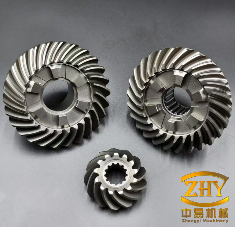
I treated the failed screw gears as a system problem rather than as an isolated material defect. In a drive axle, screw gears transmit torque under alternating bending, contact, and friction loads. The tooth root experiences repeated bending stress, the tooth flank experiences contact stress, and relative sliding produces friction and wear. For the failed screw gears, the fracture position and fracture surface features pointed clearly to bending fatigue rather than to overload, wear, or contact fatigue. I therefore focused on the root fillet, meshing pattern, core hardness, and load distribution because these variables control the bending fatigue strength of screw gears.
Observed failure condition of the screw gears. I recorded the failure condition of the screw gears and summarized the main observations in Table 1. All failed teeth broke from the tooth root, and each fracture left a short unbroken section near the large end. The fracture surfaces were concave in shape. Magnetic particle inspection revealed additional cracks at the convex-side root of teeth that had not yet broken. These cracks ran approximately parallel to the tooth root, and their orientation was slightly higher at the small end and lower at the large end. When I sectioned a failed screw gear perpendicular to the crack length, polished the section, and examined it, I found that the crack originated at the transition between the root fillet and the tooth flank. This location is a classic stress concentration site in screw gears.
| Failure record | Service time | Fracture position | Crack origin | Fracture surface shape | Unbroken section | Failure mode |
|---|---|---|---|---|---|---|
| Screw gear 1 | 200–1300 h range | Tooth root | Root fillet to tooth flank transition | Concave | Large end | Bending fatigue fracture |
| Screw gear 2 | 200–1300 h range | Tooth root | Root fillet to tooth flank transition | Concave | Large end | Bending fatigue fracture |
| Screw gear 3 | 200–1300 h range | Tooth root | Root fillet to tooth flank transition | Concave | Large end | Bending fatigue fracture |
Macroscopic and crack path observations for the screw gears. I found that the cracks in the unbroken teeth of the screw gears followed the same general path as the fracture lines on the broken teeth. The crack path was not random. It started near the root of the convex side, propagated along the tooth width at the root region, and then turned toward the tooth thickness direction in the interior of the tooth. This path is consistent with a tooth root bending fatigue mechanism in screw gears. The small end of the tooth was more severely loaded or more crack-sensitive than the large end, because the crack reached the small end earlier, while a short section at the large end remained unbroken. The residual large-end section was therefore not evidence of a different failure mode; it was the final fast-fracture region left after the fatigue crack had already reduced the load-bearing section.
Fracture surface analysis of the screw gears. I examined the fracture surfaces by scanning electron microscopy. The fracture surfaces contained many fatigue arc lines. Fatigue arc lines are one of the most fundamental features of fatigue fracture, so I concluded that the failure mode of the screw gears was bending fatigue fracture. Near the tooth root, the fatigue arc lines were approximately perpendicular to the tooth width direction. In the middle of the tooth, the fatigue arc lines were approximately parallel to the tooth width direction. Because the normal to a fatigue arc line indicates the local crack growth direction, I concluded that the fatigue crack in the screw gears first propagated along the tooth width near the root and then propagated along the tooth thickness inside the tooth. This observation is important because it shows that the root fillet geometry and root stress state controlled crack initiation and early crack growth.
| Fracture surface region | Dominant feature | Interpretation for screw gears | Crack growth direction |
|---|---|---|---|
| Near tooth root | Fatigue arc lines perpendicular to tooth width | Root bending stress drove early fatigue crack growth | Along tooth width |
| Middle of tooth | Fatigue arc lines parallel to tooth width | Crack turned into the tooth interior | Along tooth thickness |
| Large end residual zone | Final fast fracture | Remaining ligament failed after fatigue crack reduced section | Final rupture |
| Small end zone | Earlier crack arrival | Small end was more sensitive to crack growth | Rapid crack extension |
Chemical composition of the screw gears. I selected three failed screw gears and analyzed their chemical composition. The results are shown in Table 2. All measured elements were within the applicable specification for 20CrMnTi steel. I therefore did not find evidence that the early tooth fracture of the screw gears was caused by a wrong steel grade, a major alloying error, or harmful residual element levels. The chemical composition was acceptable, so the failure mechanism had to be explained by geometry, heat treatment, hardness distribution, load distribution, or a combination of these factors.
| Sample | C | Si | Mn | S | P | Cr | Ti |
|---|---|---|---|---|---|---|---|
| Screw gear 1 | 0.20 | 0.26 | 0.89 | 0.024 | 0.032 | 1.05 | 0.05 |
| Screw gear 2 | 0.22 | 0.24 | 0.92 | 0.027 | 0.031 | 1.01 | 0.05 |
| Screw gear 3 | 0.19 | 0.27 | 0.95 | 0.018 | 0.018 | 1.11 | 0.05 |
| Standard range | 0.17–0.23 | 0.17–0.37 | 0.80–1.10 | ≤0.035 | ≤0.030 | 1.00–1.30 | 0.04–0.10 |
Hardness and metallographic results for the screw gears. I measured surface hardness and core hardness on the selected failed screw gears. The surface hardness met the technical requirement of 58–64 HRC. However, the core hardness was either below the lower limit or only just at the lower limit of the required 33–45 HRC. The measured values were 33, 31, and 31 HRC. This result was significant because a low core hardness reduces the support that the core provides to the hardened case. In carburized or surface-hardened screw gears, the case resists fatigue crack initiation, while the core supports the case and resists crack growth. A weak core allows the case to bend more easily under load, increasing the stress at the root fillet and accelerating fatigue failure of the screw gears.
| Sample | Surface hardness / HRC | Core hardness / HRC | Surface hardness requirement | Core hardness requirement | Assessment |
|---|---|---|---|---|---|
| Screw gear 1 | 62 | 33 | 58–64 HRC | 33–45 HRC | Surface acceptable; core at lower limit |
| Screw gear 2 | 60 | 31 | 58–64 HRC | 33–45 HRC | Surface acceptable; core below requirement |
| Screw gear 3 | 60 | 31 | 58–64 HRC | 33–45 HRC | Surface acceptable; core below requirement |
I also reviewed the metallographic levels of the screw gears for carbide, martensite plus retained austenite, and core ferrite. The reported levels were within the general gear material and heat-treatment requirements. Therefore, the main heat-treatment issue was not an obvious carbide network, excessive retained austenite, or unacceptable ferrite banding. The more important problem was the core hardness level. For screw gears, a low core hardness can exist even when the case hardness is acceptable, and this combination is dangerous because the surface appears to pass inspection while the overall tooth bending fatigue resistance is reduced.
| Microstructural item | Requirement for screw gears | Observed condition | Effect on tooth fracture risk |
|---|---|---|---|
| Carbide level | Within specified gear limits | Acceptable | No primary evidence of carbide-induced cracking |
| Martensite plus retained austenite | Within specified gear limits | Acceptable | No primary evidence of retained-austenite instability |
| Core ferrite | Within specified gear limits | Acceptable | No primary evidence of ferrite-controlled soft core |
| Core hardness | 33–45 HRC | 31–33 HRC | Reduced support of case and lower bending fatigue strength |
Bending stress analysis for the screw gears. I treated each tooth of the screw gears as a cantilever beam of width equal to the face width. Under alternating load, the tensile side of the root fillet experiences the highest bending stress. When the local stress exceeds the fatigue limit of the material, a fatigue crack initiates. The crack then grows under repeated loading until the remaining section fractures. For the screw gears, the fracture position and fatigue arc lines confirmed this mechanism. The nominal tooth root bending stress can be written as
$$ \sigma_F = \frac{K F_n}{b m Y_S} = \frac{2 K T_1}{b m d_1 Y_S} $$
where \(\sigma_F\) is the tooth root bending stress, \(F_n\) is the normal working force, \(b\) is the face width, \(m\) is the module, \(K\) is the load factor, \(T_1\) is the rated torque, \(d_1\) is the pinion diameter, and \(Y_S\) is the tooth root stress concentration factor. The stress concentration factor depends strongly on the root fillet geometry. I used the following relationships to evaluate the effect of the root fillet:
$$ Y_S = (1.2 + 0.31 L_0) q_s^{\,1/[1.21 + (2.3/L_0)]} $$
$$ L_0 = \frac{s}{l} $$
$$ q_s = \frac{s}{2\rho_F} $$
In these equations, \(s\) is the tooth thickness at the critical root section, \(l\) is the tooth height, and \(\rho_F\) is the root fillet curvature radius. The variable \(q_s\) increases when the root fillet curvature radius decreases. A larger \(q_s\) produces a larger stress concentration factor \(Y_S\), which directly increases the root bending stress in the screw gears. Therefore, if all other parameters remain constant, the root fillet curvature radius is a primary control variable for the bending fatigue life of screw gears.
| Symbol | Meaning | Influence on screw gear root stress |
|---|---|---|
| \(\sigma_F\) | Tooth root bending stress | Higher value accelerates fatigue crack initiation |
| \(F_n\) | Normal working force | Higher value increases root stress |
| \(b\) | Face width | Larger width reduces nominal stress but can worsen misalignment |
| \(m\) | Module | Larger module increases tooth section and reduces stress |
| \(K\) | Load factor | Higher dynamic or shock load increases root stress |
| \(Y_S\) | Root stress concentration factor | Controlled strongly by root fillet radius |
| \(\rho_F\) | Root fillet curvature radius | Smaller radius raises stress concentration |
| \(L_0\) | Tooth shape parameter | Describes tooth thickness-to-height ratio |
| \(q_s\) | Root fillet parameter | Increases as fillet radius decreases |
Root fillet curvature radius of the screw gears. I measured the root fillet curvature radius of the failed screw gears using an optical projector. Both the large end and the small end had a root fillet curvature radius of approximately 2.2 mm. This value was too small for the load level and tooth size of the screw gears. A small root fillet radius creates a sharp geometric transition between the root and the tooth flank. Under bending load, the stress lines crowd into this transition, producing a local stress peak. The result is early fatigue crack initiation at the root fillet. Published gear experience shows that increasing the root fillet curvature radius can significantly increase bending fatigue life. For example, increasing the root fillet radius from 0.75 mm to 1.5 mm can increase the bending fatigue life by approximately three times. For the failed screw gears, the measured 2.2 mm radius was still insufficient for the actual load spectrum, and the crack origin at the root fillet confirmed this conclusion.
| Root fillet condition | Relative stress concentration | Expected fatigue behavior of screw gears | Assessment for failed screw gears |
|---|---|---|---|
| Very small radius | Very high | Early crack initiation at root | Not acceptable |
| Small radius | High | Reduced bending fatigue life | Observed condition |
| Moderate radius | Medium | Improved fatigue life | Intermediate improvement |
| Large radius | Low | Delayed crack initiation | Preferred direction |
| Optimized radius with smooth transition | Lowest practical | Best bending fatigue resistance | Final improvement target |
Meshing spot and load distribution in the screw gears. I measured the meshing spot of the screw gears during operation. The actual meshing spot was clearly smaller than the required size in the face width direction. For screw gears with a precision grade of 7–8, the contact pattern should be located in the middle of the tooth flank, with a length not less than 70% of the full face width and a height not less than 60% of the full tooth height. The failed screw gears did not meet this requirement. A small meshing spot concentrates the load on a limited area of the tooth flank. This creates edge contact, local overload, and additional bending moment at the root. Even if the nominal bending stress is acceptable, the actual local stress at the root can become much higher because of misalignment and poor load sharing. In screw gears, a poor meshing spot is therefore not only a contact problem; it is also a root bending fatigue problem.
| Meshing spot parameter | Required condition for screw gears | Observed condition | Consequence |
|---|---|---|---|
| Location | Middle of tooth flank | Not fully centered | Edge loading and local stress rise |
| Length along face width | ≥70% of full face width | Clearly smaller | Reduced load-sharing area |
| Height along tooth height | ≥60% of full tooth height | Insufficient | Higher contact pressure and bending moment |
| Contact distribution | Smooth and central | Concentrated | Accelerated fatigue crack initiation |
| Effect on root stress | Uniform load distribution | Non-uniform load distribution | Increased effective root bending stress |
I also considered the load distribution factor used in gear bending stress calculations. In a more complete form, the bending stress of screw gears can be expressed as
$$ \sigma_F = \frac{F_t}{b m_n} Y_{Fa} Y_{Sa} Y_\epsilon Y_\beta K_A K_v K_{F\beta} K_{F\alpha} $$
where \(Y_{Fa}\) is the form factor, \(Y_{Sa}\) is the stress concentration factor, \(Y_\epsilon\) is the contact ratio factor, \(Y_\beta\) is the helix angle factor, \(K_A\) is the application factor, \(K_v\) is the dynamic factor, \(K_{F\beta}\) is the face load distribution factor, and \(K_{F\alpha}\) is the transverse load distribution factor. A small meshing spot increases \(K_{F\beta}\) and \(K_{F\alpha}\). The local tooth root stress therefore becomes larger than the nominal calculation predicts. For the failed screw gears, this effect combined with the small root fillet radius and low core hardness to reduce the fatigue strength below the actual service stress.
Core hardness and case support in the screw gears. I found that the low core hardness of the screw gears was another important contributor to early tooth fracture. The case provides wear resistance and contact fatigue resistance, while the core provides strength and support. When the core hardness is too low, the case can deflect more under bending load. This increases the tensile stress at the root fillet and makes the case more likely to crack. A simple way to describe the benefit of core hardness is to treat the allowable bending fatigue strength as an increasing function of core hardness:
$$ \sigma_{F\lim} = \sigma_{F\lim,0} + c_H (HV_{\text{core}} – HV_{\text{ref}}) $$
Here, \(\sigma_{F\lim}\) is the allowable bending fatigue strength, \(\sigma_{F\lim,0}\) is a reference value, \(HV_{\text{core}}\) is the core hardness, \(HV_{\text{ref}}\) is a reference hardness, and \(c_H\) is a positive coefficient. The exact coefficient depends on material, case depth, and load spectrum, but the trend is clear: within the specified range, higher core hardness increases the support of the case and improves the bending fatigue life of screw gears. In the failed screw gears, the core hardness was at or below the lower limit, so the support effect was insufficient.
| Core hardness condition | Support to case | Root bending resistance | Risk of early tooth fracture in screw gears |
|---|---|---|---|
| Below specification | Weak | Low | High |
| At lower specification limit | Marginal | Marginal | Moderate to high |
| Middle of specification | Adequate | Good | Moderate |
| Upper half of specification | Strong | High | Low |
| Excessively high with brittleness risk | Very strong but toughness may drop | Depends on toughness | Needs balanced control |
Fatigue crack growth in the screw gears. Once a fatigue crack initiated at the root fillet of a screw gear, it grew under repeated bending. I used fracture mechanics concepts to describe the growth stage. The crack-driving force can be represented by the stress intensity range:
$$ \Delta K = Y \Delta\sigma \sqrt{\pi a} $$
where \(\Delta K\) is the stress intensity range, \(Y\) is a geometry factor, \(\Delta\sigma\) is the applied stress range, and \(a\) is the crack length. The crack growth rate can be described by the Paris relationship:
$$ \frac{da}{dN} = C (\Delta K)^m $$
in which \(C\) and \(m\) are material constants and \(N\) is the number of load cycles. For the failed screw gears, the small root fillet radius increased \(\Delta\sigma\) at the crack origin. The low core hardness reduced the resistance to crack growth. The poor meshing spot increased the local load and therefore increased \(\Delta K\). These effects combined to produce a relatively short fatigue life. The crack first grew along the tooth width near the root, then turned into the tooth thickness direction, and finally left a short unbroken section at the large end. This sequence matches the fracture surface observations and the crack path found in the unbroken teeth.
| Fatigue stage | Driving variable in screw gears | Observed feature | Effect of poor design or process condition |
|---|---|---|---|
| Crack initiation | Local root stress, stress concentration | Root fillet origin | Small fillet radius increases initiation risk |
| Early growth | Stress intensity range | Fatigue arc lines | Poor meshing spot increases local stress range |
| Stable growth | Paris law behavior | Crack along tooth width then thickness | Low core hardness reduces crack growth resistance |
| Final fracture | Reduced remaining section | Unbroken large-end ligament | Final fast fracture after fatigue crack growth |
Root cause ranking for the screw gears. I ranked the root causes according to their contribution to the early tooth fracture. The primary causes were the small root fillet curvature radius, the undersized meshing spot, and the low core hardness. The secondary causes included normal material hardenability variation, possible heat-treatment control variation, and manufacturing tolerance stack-up. The chemical composition and general microstructure were acceptable, so I did not classify them as primary causes. The failure was therefore a design and process interaction problem rather than a simple material certification problem. For screw gears, this distinction is important because improving only one variable may not be sufficient if the other variables remain marginal.
| Rank | Root cause | Evidence from screw gears | Effect on fatigue life | Priority |
|---|---|---|---|---|
| 1 | Small root fillet curvature radius | Measured about 2.2 mm; crack origin at root fillet | Strong increase in stress concentration | High |
| 2 | Undersized meshing spot | Contact pattern smaller than required | Non-uniform load and edge contact | High |
| 3 | Low core hardness | Measured 31–33 HRC against 33–45 HRC | Weak support of hardened case | High |
| 4 | Hardenability variation | Core hardness scatter among screw gears | Unstable fatigue performance | Medium |
| 5 | Manufacturing tolerance stack-up | Meshing spot not centered or large enough | Local load concentration | Medium |
| 6 | Surface integrity factors | No dominant defect found, but improvement still useful | Moderate effect on crack initiation | Medium |
Failure sequence of the screw gears. Based on the inspection results, I reconstructed the failure sequence of the screw gears. First, the screw gears operated under alternating bending stress. Second, because the root fillet curvature radius was too small, a local stress concentration developed at the transition between the root fillet and the tooth flank. Third, because the meshing spot was undersized, the load was not distributed evenly across the face width, which further increased the local stress. Fourth, because the core hardness was low, the case did not receive enough support, so the root fillet strain increased. Fifth, a fatigue crack initiated at the convex-side root near the middle-to-small-end region. Sixth, the crack grew along the tooth width at the root and then turned into the tooth thickness direction. Seventh, the crack reached the small end earlier, while the large end still had a short unbroken ligament. Finally, the remaining section fractured suddenly. This sequence explains both the fracture position and the residual large-end section observed in the failed screw gears.
| Step | Event in screw gears | Controlling condition | Result |
|---|---|---|---|
| 1 | Alternating bending load | Drive axle torque and road load | Repeated root stress |
| 2 | Stress concentration at root | Small root fillet radius | Local stress peak |
| 3 | Non-uniform load distribution | Small meshing spot | Edge contact and higher local load |
| 4 | Reduced case support | Low core hardness | Higher root strain |
| 5 | Crack initiation | Root fillet transition | Fatigue crack start |
| 6 | Stable crack growth | Repeated bending cycles | Fatigue arc lines and crack path |
| 7 | Final fracture | Reduced remaining section | Tooth fracture of screw gears |
Improvement measures for the screw gears. I proposed and implemented several improvements for the screw gears. First, I changed the gear cutting tool to a tool with a larger tip radius so that the root fillet curvature radius could be increased. I increased the root fillet curvature radius from approximately 2.2 mm to 3.5 mm. Second, I tightened the inspection of the screw gears and their mating bevel gears to ensure that the meshing spot met the required size and position. Third, I changed the material from conventional 20CrMnTi steel to 20CrMnTiH steel with controlled hardenability so that the core hardness could be stabilized within the required range. Fourth, I adjusted the tooth form to improve the load distribution and root geometry. Fifth, I added a strong shot peening process to introduce compressive residual stress at the root surface and improve the bending fatigue strength of the screw gears.
| Improvement | Change made | Mechanism of improvement | Effect on screw gears |
|---|---|---|---|
| Root fillet optimization | Larger cutter tip radius; fillet radius increased to 3.5 mm | Lower stress concentration factor | Delayed root fatigue crack initiation |
| Meshing spot control | Better matching and inspection of screw gears and mating gears | More uniform load distribution | Reduced edge loading and local bending stress |
| Material hardenability control | Use of 20CrMnTiH steel | More stable core hardness | Improved case support and fatigue strength |
| Tooth form adjustment | Modified tooth shape | Improved contact and root geometry | Lower dynamic load and root stress |
| Strong shot peening | Added surface treatment | Compressive residual stress at root | Increased resistance to fatigue crack initiation |
Effect of root fillet improvement in the screw gears. The root fillet improvement was based on the relationship between fillet radius and stress concentration. Increasing the fillet radius reduces \(q_s\), which reduces \(Y_S\), which in turn reduces the root bending stress \(\sigma_F\). A larger fillet also reduces the stress gradient near the root surface, so the highly stressed volume becomes smaller. For the screw gears, the increased fillet radius from 2.2 mm to 3.5 mm gave a smoother transition between the root and the tooth flank. This reduced the local stress peak and delayed fatigue crack initiation. I also confirmed that the larger fillet did not interfere with the mating tooth profile or the required meshing spot.
| Root fillet radius condition | Stress concentration factor trend | Root stress trend | Expected fatigue life of screw gears |
|---|---|---|---|
| 2.2 mm initial condition | High | High | Early fracture observed |
| 3.0 mm intermediate | Moderate | Moderate | Improved but not final target |
| 3.5 mm final condition | Lower | Lower | Required life achieved |
| Further increase if geometry permits | Lowest practical | Lowest practical | Additional potential benefit |
Shot peening effect in the screw gears. I added strong shot peening because it introduces compressive residual stress into the surface layer. The effective stress at the root becomes the sum of the applied stress and the residual stress:
$$ \sigma_{\text{eff}} = \sigma_{\text{applied}} + \sigma_{\text{res}} $$
If \(\sigma_{\text{res}}\) is compressive, meaning negative in sign, the effective tensile stress at the root is reduced. A common fatigue criterion can be written as
$$ K_t \sigma_{\text{nom}} + \sigma_{\text{res}} \le \sigma_{-1} $$
where \(K_t\) is the elastic stress concentration factor, \(\sigma_{\text{nom}}\) is the nominal bending stress, \(\sigma_{\text{res}}\) is the residual stress, and \(\sigma_{-1}\) is the fatigue limit. By making the residual stress more compressive, I increased the margin against fatigue crack initiation in the screw gears. Shot peening also creates a work-hardened surface layer, which can further resist crack initiation. This measure was especially useful because the root fillet of a screw gear is difficult to strengthen by other means after machining.
| Surface condition | Residual stress state at root | Effective tensile stress | Fatigue crack initiation risk in screw gears |
|---|---|---|---|
| Untreated machined surface | Low or slightly tensile | Higher | Higher |
| Conventional shot peening | Compressive | Lower | Moderate reduction |
| Strong shot peening | High compressive | Lowest practical | Significant reduction |
| Improper peening with surface damage | Variable | Unreliable | Not acceptable |
Material and heat-treatment improvement for the screw gears. I recommended 20CrMnTiH steel because its hardenability is controlled more tightly than that of conventional 20CrMnTi steel. Controlled hardenability makes it easier to obtain a stable core hardness within the 33–45 HRC range after quenching. A stable core hardness improves the support of the case and reduces scatter in bending fatigue life among screw gears. In addition, I reviewed the heat-treatment process to ensure that the quenching and tempering conditions were consistent with the required case depth and core hardness. The goal was not simply to increase surface hardness; the goal was to produce a balanced hardness profile in the screw gears, with a hard surface for contact fatigue resistance and a strong, tough core for bending fatigue resistance.
| Material or process factor | Initial condition | Improved condition | Benefit for screw gears |
|---|---|---|---|
| Steel grade | 20CrMnTi | 20CrMnTiH | Better hardenability control |
| Core hardness | 31–33 HRC | Stabilized within 33–45 HRC | Stronger support of case |
| Surface hardness | 60–62 HRC | Maintained 58–64 HRC | Wear and contact fatigue resistance |
| Case depth | Within requirement but variable | Controlled and consistent | Balanced case-core performance |
| Heat-treatment control | Standard control | Tighter control | Reduced property scatter |
Meshing spot control and gear matching for the screw gears. I treated the meshing spot as a critical quality characteristic for the screw gears. A proper meshing spot is located in the middle of the tooth flank, extends along at least 70% of the face width, and covers at least 60% of the tooth height. When the meshing spot is too small, the load is concentrated on a narrow band. This increases the local bending moment at the root and can shift the crack initiation site toward the edge of the contact zone. For the screw gears, I required both the large screw gear and the mating bevel gear to be inspected together. I also required the assembly to be checked for shaft alignment, bearing clearance, and housing distortion because these factors can move the contact pattern and reduce the effective meshing area. The improved meshing spot reduced the face load distribution factor and improved the bending fatigue life of the screw gears.
| Meshing spot control item | Requirement for screw gears | Inspection method | Action if not met |
|---|---|---|---|
| Pattern location | Central on tooth flank | Contact pattern test | Adjust mounting distance and alignment |
| Length along face | ≥70% of face width | Visual or marking compound | Correct tooth form or assembly position |
| Height along tooth | ≥60% of tooth height | Visual or marking compound | Check tooth profile and load condition |
| Pattern continuity | Smooth and uninterrupted | Contact pattern test | Correct misalignment or local interference |
| Edge contact | Not permitted | Visual inspection | Reject or rework screw gears |
Verification after improvement of the screw gears. After applying the improvements, I followed the performance of the revised screw gears through installation and field testing. The root fillet radius was increased to 3.5 mm, the material was changed to 20CrMnTiH steel, the tooth form was adjusted, and strong shot peening was added. The meshing spot was controlled to meet the required size and position. The improved screw gears exceeded the specified service life of 2000 h and did not show early tooth fracture. I also observed that the core hardness was more stable and that the contact pattern was more centered and larger than before. These results confirmed that the failure analysis was correct and that the improvement measures addressed the dominant causes of tooth fracture in the screw gears.
| Parameter | Initial screw gears | Improved screw gears | Result |
|---|---|---|---|
| Root fillet radius | About 2.2 mm | 3.5 mm | Lower stress concentration |
| Steel grade | 20CrMnTi | 20CrMnTiH | More stable core hardness |
| Core hardness | 31–33 HRC | Within 33–45 HRC | Better case support |
| Surface hardness | 60–62 HRC | Within 58–64 HRC | Maintained wear resistance |
| Meshing spot | Smaller than required | Required size and central position | More uniform load distribution |
| Shot peening | Not used or not strong enough | Strong shot peening applied | Compressive residual stress at root |
| Service life | 200–1300 h before fracture | Beyond 2000 h | No early tooth fracture |
Design review checklist for screw gears. I developed a design review checklist to prevent similar early tooth fracture in other screw gears. The checklist focuses on root fillet radius, meshing spot, core hardness, case depth, tooth form, material hardenability, and residual stress. For screw gears, it is not enough to verify only the surface hardness. The core hardness and root geometry must be controlled because they determine the bending fatigue resistance. The checklist also includes assembly alignment and contact pattern verification because the actual load distribution in a drive axle can differ from the nominal design condition. I found that this checklist helped integrate failure analysis findings into the development process for screw gears.
| Review item | Question for screw gears | Acceptance criterion | Risk if not controlled |
|---|---|---|---|
| Root fillet radius | Is the radius large enough for the load? | Optimized by stress analysis and test | High root stress concentration |
| Meshing spot | Is the contact pattern central and large enough? | ≥70% face width and ≥60% tooth height | Edge loading and non-uniform stress |
| Core hardness | Is the core hardness within the required range? | 33–45 HRC | Weak support of hardened case |
| Surface hardness | Is the case hard enough for contact fatigue? | 58–64 HRC | Wear and contact fatigue risk |
| Material hardenability | Is hardenability controlled? | Controlled steel grade | Scatter in core properties |
| Shot peening | Is compressive residual stress introduced? | Validated peening process | Higher crack initiation risk |
| Assembly alignment | Are shaft and bearing conditions correct? | Within alignment specification | Contact pattern shift |
Comparison with general screw gear failure modes. I compared the observed failure with common failure modes of screw gears. Bending fatigue fracture usually starts at the root fillet and produces fatigue arc lines. Contact fatigue usually starts on the tooth flank and produces pitting or spalling. Wear usually changes the tooth profile and may produce polishing or scratching. Overload fracture usually produces a rougher fracture surface with less fatigue evidence. The failed screw gears showed a clear root origin and fatigue arc lines, so I classified the failure as bending fatigue fracture. The contributing factors were poor root geometry, non-uniform load distribution, and low core hardness. This classification guided the improvement measures toward root fillet optimization, meshing spot control, material hardenability, and shot peening.
| Failure mode | Typical origin in screw gears | Typical feature | Observed in this investigation |
|---|---|---|---|
| Bending fatigue fracture | Tooth root fillet | Fatigue arc lines, final fracture zone | Yes |
| Contact fatigue | Tooth flank | Pitting, spalling, subsurface cracks | Not primary |
| Wear | Tooth flank | Profile loss, polishing, scratching | Not primary |
| Overload fracture | Root or tooth body | Rough surface, little fatigue growth | Not primary |
| Case-core separation | Case-core boundary | Subsurface crack, spalling | Not primary |
Manufacturing control for screw gears. I identified several manufacturing controls that are necessary for reliable screw gears. The gear cutting tool must produce the specified root fillet radius. The heat-treatment furnace must maintain stable temperature and atmosphere so that case depth and core hardness remain within specification. The quenching process must provide sufficient cooling to achieve the required core hardness without introducing unacceptable distortion or cracking. The assembly process must set the correct mounting distance and contact pattern. The inspection process must measure the root fillet radius, core hardness, surface hardness, case depth, and meshing spot. For screw gears, these controls are linked; a change in one process can shift the contact pattern or the hardness profile and affect the bending fatigue life.
| Manufacturing stage | Control variable | Target for screw gears | Inspection method |
|---|---|---|---|
| Forging or bar preparation | Material grade and hardenability | 20CrMnTiH with controlled hardenability | Certification and hardenability test |
| Gear cutting | Root fillet radius | 3.5 mm or optimized value | Optical projector or profile measurement |
| Heat treatment | Core hardness | 33–45 HRC | Hardness test on sectioned sample |
| Heat treatment | Surface hardness | 58–64 HRC | Hardness test |
| Heat treatment | Case depth and microstructure | Within gear specification | Metallographic examination |
| Shot peening | Residual stress and coverage | Validated compressive stress | Almen strip and X-ray diffraction if required |
| Assembly | Meshing spot | Central, ≥70% face width, ≥60% tooth height | Contact pattern test |
Stress concentration and geometry equations for screw gears. I used additional equations to summarize the geometric effects in the screw gears. The nominal bending stress at the root can be approximated as
$$ \sigma_{\text{nom}} = \frac{M_b c}{I} = \frac{6 F_t h_a}{b s^2} $$
where \(M_b\) is the bending moment, \(c\) is the distance from the neutral axis to the tensile surface, \(I\) is the section moment of inertia, \(F_t\) is the tangential force, \(h_a\) is the moment arm, \(b\) is the face width, and \(s\) is the root thickness. The maximum local stress is then
$$ \sigma_{\max} = K_t \sigma_{\text{nom}} $$
Here, \(K_t\) is the stress concentration factor. A small root fillet radius increases \(K_t\). For the failed screw gears, the measured radius of about 2.2 mm produced a high \(K_t\), and the crack initiated at the point of maximum local stress. Increasing the radius to 3.5 mm reduced \(K_t\) and lowered \(\sigma_{\max}\). The meshing spot also influenced \(\sigma_{\text{nom}}\) because a smaller contact area increased \(F_t\) per unit width and increased the effective moment arm. The low core hardness reduced the load-bearing capacity of the tooth body and allowed additional deflection, which further raised the local stress at the root fillet.
| Equation | Purpose for screw gears | Key variable | Failure implication |
|---|---|---|---|
| \(\sigma_F = \frac{2 K T_1}{b m d_1 Y_S}\) | Estimate root bending stress | \(Y_S\) | Small fillet radius increases \(Y_S\) |
| \(Y_S = (1.2 + 0.31 L_0) q_s^{1/[1.21 + (2.3/L_0)]}\) | Evaluate stress concentration | \(q_s\) | Small \(\rho_F\) increases \(q_s\) and \(Y_S\) |
| \(q_s = \frac{s}{2\rho_F}\) | Relate geometry to fillet radius | \(\rho_F\) | Small \(\rho_F\) raises root stress |
| \(\sigma_{\text{nom}} = \frac{6 F_t h_a}{b s^2}\) | Approximate cantilever bending | \(s\) | Thin root section increases stress |
| \(\sigma_{\max} = K_t \sigma_{\text{nom}}\) | Include local stress concentration | \(K_t\) | Sharp fillet increases \(K_t\) |
| \(\Delta K = Y \Delta\sigma \sqrt{\pi a}\) | Describe crack driving force | \(\Delta\sigma\) | Higher stress range accelerates crack growth |
| \(\frac{da}{dN} = C (\Delta K)^m\) | Describe fatigue crack growth | \(\Delta K\) | Higher \(\Delta K\) shortens fatigue life |
Load factor effects in screw gears. I also considered the load factors that can increase the actual stress in screw gears beyond the nominal design value. The application factor \(K_A\) accounts for external shock and duty cycle. The dynamic factor \(K_v\) accounts for vibration and speed. The face load distribution factor \(K_{F\beta}\) accounts for non-uniform load across the face width. The transverse load distribution factor \(K_{F\alpha}\) accounts for load sharing between teeth. In the failed screw gears, the small meshing spot indicated that \(K_{F\beta}\) and \(K_{F\alpha}\) were larger than desired. The root fillet radius controlled the stress concentration factor \(Y_S\). The core hardness controlled the support and the effective load-carrying capacity of the tooth body. Therefore, the product of these factors determined whether the screw gears could survive the service load spectrum. A marginal design in any one factor may be tolerated if other factors are strong, but the failed screw gears were marginal or poor in several factors at the same time.
| Load factor | Meaning | Condition in failed screw gears | Improvement action |
|---|---|---|---|
| \(K_A\) | Application and shock factor | Drive axle service load | Use realistic load spectrum |
| \(K_v\) | Dynamic factor | Potential vibration and speed effects | Improve tooth form and assembly |
| \(K_{F\beta}\) | Face load distribution factor | High due to small meshing spot | Center and enlarge contact pattern |
| \(K_{F\alpha}\) | Transverse load distribution factor | Affected by tooth matching | Control tooth profile and alignment |
| \(Y_S\) | Root stress concentration factor | High due to small root fillet | Increase fillet radius |
| \(Y_{Fa}\) and \(Y_{Sa}\) | Form and stress concentration factors | Geometry-controlled | Adjust tooth form |
Reliability perspective for screw gears. I viewed the failure of the screw gears from a reliability perspective. The service life of a screw gear is not determined by a single average property. It is determined by the weakest combination of stress, geometry, material, and manufacturing variation. The failed screw gears had acceptable chemical composition and acceptable surface hardness, but they had a weak root geometry, an undersized contact pattern, and a low core hardness. These three factors interacted. The root fillet radius determined how concentrated the stress would be. The meshing spot determined how large the actual load would be at the critical tooth position. The core hardness determined how well the tooth body could support the case. When these factors were all unfavorable, the fatigue life fell below the required 2000 h. The improvements addressed all three factors, which is why the revised screw gears performed reliably.
| Reliability factor | Failed screw gears | Improved screw gears | Effect on life distribution |
|---|---|---|---|
| Root stress concentration | High | Reduced | Longer crack initiation life |
| Contact load distribution | Non-uniform | More uniform | Lower local stress amplitude |
| Core support | Weak | Stronger and stable | Slower damage accumulation |
| Residual stress at root | Not beneficial enough | Compressive | Higher fatigue limit |
| Manufacturing scatter | Higher | Lower | More predictable life |
Practical conclusions from the screw gear investigation. I concluded that the early tooth fracture of the screw gears was a bending fatigue failure driven by stress concentration at the root fillet. The small root fillet curvature radius was the most direct geometric cause. The undersized meshing spot increased the effective load at the root and worsened the stress concentration. The low core hardness reduced the support of the case and lowered the fatigue resistance of the tooth body. Chemical composition and general microstructure were acceptable, so material grade error was not the primary cause. The fracture surface features, crack path, and crack origin all supported the bending fatigue mechanism. The improvements increased the root fillet radius, controlled the meshing spot, stabilized the core hardness, adjusted the tooth form, and added strong shot peening. The revised screw gears exceeded the required 2000 h service life and did not show early tooth fracture.
Key recommendations for future screw gears. I recommend that future screw gears be designed with a root fillet radius that is validated by stress analysis and fatigue testing, not simply by manufacturing convenience. I recommend that the meshing spot be treated as a critical characteristic and verified after assembly. I recommend that core hardness be specified and controlled with a hardenability-controlled steel such as 20CrMnTiH. I recommend that shot peening be applied to the root fillet when the bending fatigue margin is limited. I recommend that fracture analysis be used whenever early tooth fracture occurs in screw gears, because the crack origin and crack path can distinguish bending fatigue from contact fatigue, wear, or overload. I also recommend that the root fillet, meshing spot, and core hardness be reviewed together because they interact strongly in screw gears.
| Recommendation | Reason for screw gears | Verification method | Expected benefit |
|---|---|---|---|
| Validate root fillet radius | Controls stress concentration | Stress analysis and fatigue test | Higher bending fatigue life |
| Control meshing spot | Controls load distribution | Contact pattern test | Lower local root stress |
| Specify core hardness range | Controls case support | Section hardness test | Stable fatigue strength |
| Use hardenability-controlled steel | Reduces property scatter | Material certification | More reliable heat treatment |
| Apply shot peening | Introduces compressive stress | Process validation | Delayed crack initiation |
| Perform failure analysis | Identifies true failure mode | Fractography and metallography | Correct and focused improvement |
Final engineering position on the screw gears. I did not find evidence that the early tooth fracture of the screw gears was caused by incorrect chemical composition or by a single gross material defect. Instead, I found a combination of geometry, load distribution, and core hardness conditions that reduced the bending fatigue strength below the actual service demand. The small root fillet radius created a stress concentration at the transition between the root fillet and the tooth flank. The small meshing spot increased the local load and made the stress distribution less uniform. The low core hardness reduced the support of the hardened case. Together, these conditions caused fatigue crack initiation at the root, stable crack growth along the tooth width and then into the tooth thickness, and final fracture. The improvements addressed these conditions directly. After increasing the root fillet radius to 3.5 mm, changing to 20CrMnTiH steel, adjusting the tooth form, adding strong shot peening, and controlling the meshing spot, the screw gears achieved a service life beyond 2000 h without early tooth fracture. This outcome confirmed that the root causes had been correctly identified and that the corrective actions were effective for the screw gears.