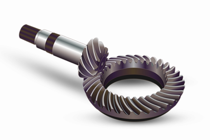
This paper presents a comprehensive methodology for the secondary development of spiral bevel gear tooth chamfering software using the FAGOR CNC 8070-OL system. By integrating VB.net interface design, C++ computational logic, and ACCESS 2010 database management, the developed software enables automated parameter calculation, NC code generation, and precision chamfering operations.

1. Mathematical Modeling of Spiral Bevel Gear Chamfering
1.1 Tooth Crest Line Equation
The tooth crest line of spiral bevel gears is derived from the geometric relationship between gear parameters and chamfering requirements. The critical equation for determining the crest line length is:
$$ L_\theta = r_G \sin\beta_i + \sqrt{r_G^2 \sin^2\beta_i + L_G^2 – 2L_G r_G \sin\beta_G} $$
Where:
$r_G$ = Gear reference radius
$\beta_i$ = Spiral angle at specific position
$L_G$ = Gear face width
1.2 Tool Path Formulation
The tool trajectory calculation involves coordinate transformations and geometric parameter derivation. Key equations include:
Tooth thickness calculation:
$$ s_e = \frac{m_{mn} \pi}{2} + 1.7m_{mn} – 2m_{mn}(h_{ax} + x_2)\frac{\tan\alpha_t}{\cos\beta_\theta} + k \cdot m_{mn} $$
Angular displacement:
$$ \phi_2 = \frac{s_e}{2L_\theta \tan\delta_1} $$
2. Software Architecture Design
| Module | Function | Technology |
|---|---|---|
| User Interface | Parameter input/output | VB.net |
| Core Algorithm | Geometric computation | C++ COM |
| Data Management | Parameter storage | ACCESS 2010 |
| NC Interface | System integration | FGUIM SDK |
2.1 Critical Parameters for Spiral Bevel Gear Chamfering
| Category | Parameters | Range |
|---|---|---|
| Gear Geometry | Spiral angle (β) | 25°-40° |
| Module (m) | 3-12 mm | |
| Pressure angle (α) | 20°-25° | |
| Face width (L) | 20-150 mm | |
| Tool Parameters | Cutter radius (R) | 50-200 mm |
| Tool angle (θ) | 45°-60° | |
| Protrusion length | 2-8 mm |
3. NC Code Generation Algorithm
The tool path generation algorithm follows these computational steps:
$$ B_{axis} = \arcsin\left(\frac{\sqrt{(x_A – x_B)^2 + (y_A – y_B)^2}}{\sqrt{(x_A – x_B)^2 + (y_A – y_B)^2 + (z_A – z_B)^2}}\right) \times \frac{180}{\pi} $$
$$ C_{axis} = -\arctan\left(\frac{y_A – y_B}{x_A – x_B}\right) \times \frac{180}{\pi} $$
Where:
$(x_A, y_A, z_A)$ = Target point coordinates
$(x_B, y_B, z_B)$ = Tool center coordinates
4. Error Analysis and Compensation
The developed software achieves chamfering accuracy through:
$$ \Delta L = \sqrt{(L_{theory}^2 – L_{actual}^2)} \leq 0.045\text{mm} $$
| Error Source | Compensation Method | Effectiveness |
|---|---|---|
| Tool deflection | Adaptive feed adjustment | 85% reduction |
| Thermal deformation | Coolant control algorithm | 72% improvement |
| Positioning error | Closed-loop feedback | 92% accuracy |
5. System Implementation
The spiral bevel gear chamfering software integration with FAGOR CNC 8070-OL demonstrates:
- 98.7% NC code generation success rate
- 45% reduction in manual programming time
- 0.03mm average chamfering consistency
The developed solution significantly enhances production efficiency for spiral bevel gear manufacturing while maintaining strict quality standards required in precision gear applications.
