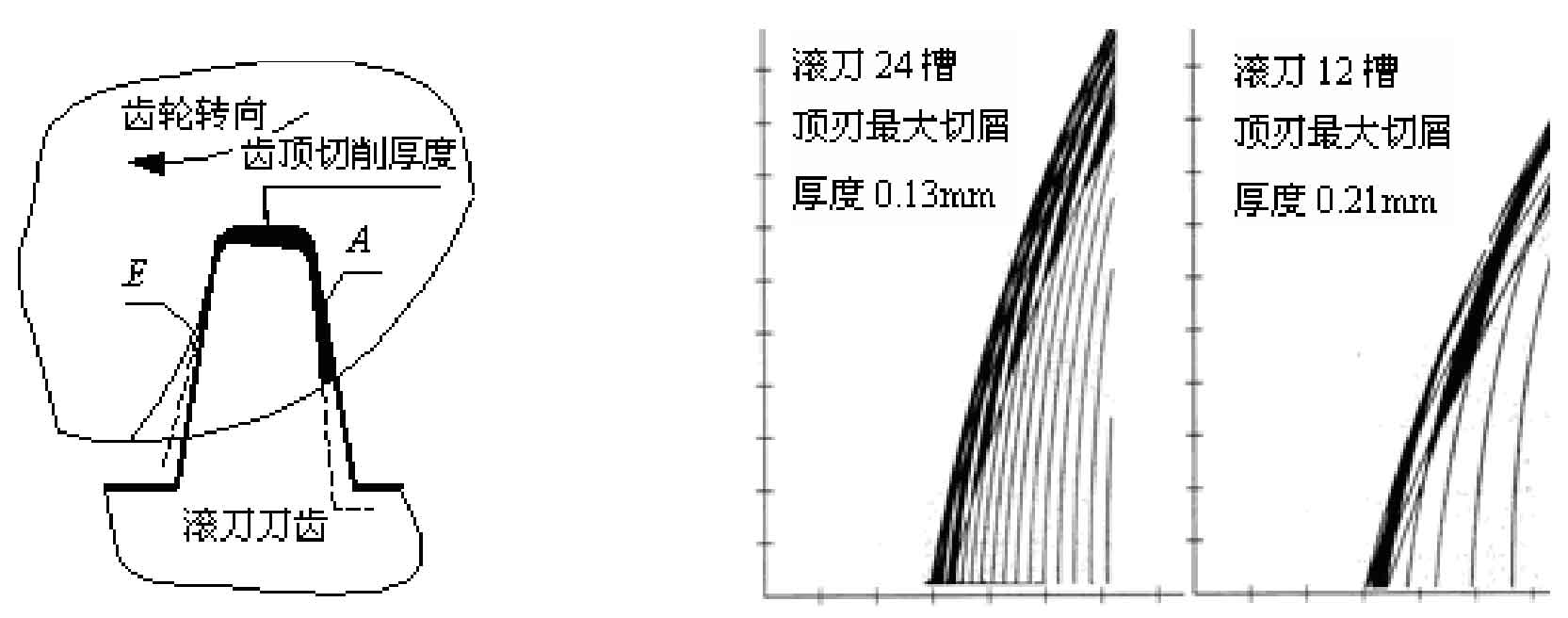
Calculate the tool travel according to Hoffmeister’s formula:
Where:
FA — axial tool path of gear hobbing cutting;
H1max – the maximum chip thickness at the tooth top of gear hobbing hob, generally 0.2mm is used to determine the axial tool walking amount;
Z2 — number of gear teeth;
IO — number of grooves of gear hobbing hob;
Zo — number of heads of gear hobbing hob;
H — cutting depth.
| Finishing method of gear after rolling | Required tool trace depth µM |
| Minimum value | Maximum value | |
| Hobbing before honing | 0 | 3 |
| Rolling and pre hobbing | 5 | 10 |
| Preshaving hobbing | 10 | 20 |
| Pre grinding hobbing | 15 | 35 |
The selection of the cutting amount of gear hobbing should be based on the reasonable chip thickness at the top of the gear hobbing hob. The restrictions of the cutting trace on the cutting amount, the rigidity of the machine tool and processing system on the cutting amount, and the comprehensive influence of the number of hob heads and slots on the cutting amount should be considered. Selection of cutting speed for gear hobbing of automobile.
Select the cutting amount according to the requirements of cutting trace, as shown in Table 1.
| Gear module | 2.5 |
| pressure angle | 20 |
| Number of gear teeth | 29 |
| Helix angle | 15 |
| correction factor | 0.2 |
| Cut in depth | 5.63 |
| Hob diameter | 110 |
| Number of grooves of hob | 24 |
The influence of other factors on the tool path is shown in Table 2: as shown in the figure, the test conditions are: the outer circle diameter of the processed workpiece is 86mm, the number of teeth is 50mm, the modulus is 2, and the axial feed rate of gear hobbing hob is 5.5mm.


