By studying the modified helical gears, it is found that selecting appropriate modification coefficients for the transmission helical gear pair can effectively improve the transmission quality of this pair of helical gears. For the reduction transmission helical gear pair, selecting the appropriate modification coefficient for the helical gear can increase the contact strength of the helical gear tooth surface, increase the bending strength of the tooth root, balance the wear of the helical gear pair tooth surface, reduce the volume of the master and slave gears, and make the corresponding gearbox structure more compact. If the modification coefficient of helical gears is not selected appropriately, their load-bearing capacity will actually decrease. Using finite element analysis method, stress numerical calculations were carried out on helical gear pairs with different modification coefficients, and the bending fatigue life of helical gears with different modification coefficients was obtained, laying the foundation for optimizing the fatigue performance of helical gear pairs in the following text.

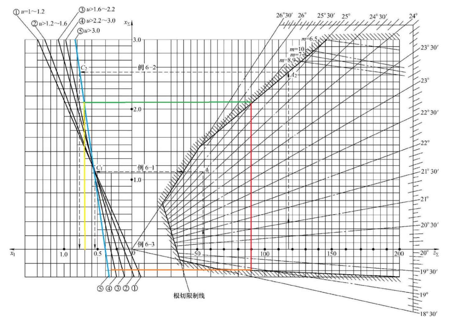
The parameters of the existing subway vehicle transmission helical gear are shown in the table. Referring to Figures in “Involute Cylindrical Gear Transmission”, it is the line diagram for selecting the modification coefficient proposed by Harbin Institute of Technology, which is superior to other types of line diagram methods currently used. This line chart is applicable to situations where the number of teeth on the small gear is greater than or equal to 12. The horizontal axis of the line graph on the right is the sum of the number of teeth in a pair of meshing gears, and the vertical axis is the total modification coefficient and 𝑥𝛴. The shaded area is the allowable zone, and when each ray in the allowable zone has the same meshing angle (such as 19 °, 20 °…, 24 °, 25 °, etc.), the total modification coefficient 𝑥𝛴 and the sum of teeth 𝑧𝛴 are a function relationship. In application, the total modification coefficient 𝑥𝛴 can be selected based on specific requirements such as the number of teeth of a pair of helical gears and the value of 𝑧𝛴 in the allowable area of the online graph. For the same number of teeth and diameter of the helical gear, when the selected total modification coefficient 𝑥𝛴 is larger (i.e. the meshing angle 𝛼 is larger), the transmission overlap 𝜀 is lower (still ensuring 𝜀 ≥ 1.2). After determining the total modification coefficient 𝑥𝛴, the helical gear modification coefficients 𝑥\1 and 𝑥\2 are allocated according to the five diagonal lines on the left side of the line graph. The vertical axis of this section still represents the total displacement coefficient 𝑥𝛴, while its horizontal axis represents the displacement coefficient 𝑥 1 of the small gear, where the interval 𝑥 1 to the left of the coordinate origin takes a positive value and the interval 𝑥 1 to the right takes a negative value. The selection range of 𝑥 1 can be determined by the total displacement coefficient 𝑥𝛴 and the tooth ratio 𝑢=(𝑧 2/𝑧 1), and thus the value range of 𝑥 2=𝑥𝛴− 𝑥 1 can be obtained. The selection and assignment of displacement coefficients based on this line graph have the following advantages:


(1) No undercutting occurs during the machining of helical gears (undercutting limits the selection of the total modification coefficient 𝑥𝛴 offline, which can also ensure that the tooth profile working section does not undergo undercutting).
(2) Tooth top thickness 𝑠𝑎>0.4 𝑚 m.
(3) The overlap degree 𝜀 ≥ 1.2.
(4) The meshing helical gears do not interfere with each other.
(5) The maximum sliding rate of the large and small gears is equal or close (𝜂 1=𝜂 2 or 𝜂 1 ≈ 𝜂 2).
(6) When selecting the total displacement coefficient 𝑥𝛴 below the modulus limit line (m=6.5, m=7, m=10, etc. in the figure), incomplete cutting will not occur when using a standard hob to machine the helical gear with this modulus.
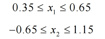
Finally, based on the selection of the modification coefficient, the line chart method is used. The selection range of the modification coefficient for the subway transmission helical gear is as follows:
The existing subway transmission helical gear modification coefficient is within the above range, which indicates that the selection range of this modification coefficient is more suitable, and the existing modification coefficient selection is more suitable. However, whether it is the optimal value within this range needs further analysis.
Firstly, based on the widely recognized line graph method, the selection range of the modification coefficients for the transmission helical gears of subway vehicles was determined, and the modification coefficients for the large and small gears were taken within the selection range. A finite element model of single tooth meshing of helical gears with different modification coefficients was established for simulation of helical gear meshing. The force state during the gear meshing process was simulated by applying torque to the small gear. The accuracy of the single tooth meshing finite element model was demonstrated by comparing the root stress of the helical gear finite element model obtained from static analysis in ABAQUS with the calculated value of the root stress of the helical gear according to GB/T 3480. By importing the results of ABAQUS static finite element analysis into the fatigue analysis software FE Safe, fatigue analysis was conducted on helical gears with different modification coefficients, and the bending fatigue life of helical gears with different modification coefficients was obtained. The following conclusions can be drawn:
(1) According to the line chart method for selecting the modification coefficient, the selection range of the subway transmission helical gear modification coefficient is -0.3 ≤ 𝑥𝛴 ≤ 1.7, 0.35 ≤ 𝑥 1 ≤ 0.65, -0.65 ≤ 𝑥 2 ≤ 1.05. The maximum sliding rates of the large and small gears of the helical gear pair within this range are equal or close, and there will be no interference between the teeth.
(2) When conducting static analysis on the single tooth meshing finite element model of the helical gear constructed in this chapter, the stress at the root of the helical gear can be accurately calculated in the meshing area of the gear teeth. The finite element results were compared with the results of GB/T 3480 “Calculation of Load Capacity of Spur and Helical Gears”. The stress error of the small gear tooth root was only -1.127%, and the stress error of the large gear tooth root was 5.387%, which can meet the accuracy requirements of tooth root stress calculation and can be used for finite element simulation of bending fatigue life.
(3) Seven sets of stress values at the root of helical gears with different modification coefficients and bending fatigue life cloud maps were obtained through finite element simulation, which can provide support for the optimization of helical gears for subway vehicle transmission with fatigue performance as the objective in Chapter 5. The variation law of root stress and bending fatigue life of large and small gears was obtained when the modification coefficient changed from small to large within the selected range. The location of the maximum tooth root stress is also the point of minimum bending fatigue life.
