
In the field of precision machinery, the rotary vector reducer stands as a critical component in various industrial applications, such as robotics, aerospace, and automated manufacturing systems. Its high transmission accuracy, compact design, and ability to handle substantial loads make it indispensable. However, achieving and maintaining high transmission accuracy in rotary vector reducers remains a significant challenge due to the cumulative effects of various errors introduced during manufacturing, assembly, and operation. These errors include part machining inaccuracies, assembly misalignments, and bearing clearances, all of which can combine in complex ways to degrade performance. In this study, I delve into the sensitivity analysis of how these error combination modes impact the dynamic transmission accuracy of rotary vector reducers. By employing a detailed mathematical model and numerical differentiation techniques, I aim to quantify the influence of each error type and its combinations, providing insights that can guide the design and manufacturing processes for enhanced precision. The findings are intended to serve as a theoretical foundation for optimizing rotary vector reducers, ensuring they meet the stringent demands of modern high-precision applications.
The core of this analysis lies in understanding the dynamic behavior of the rotary vector reducer under realistic conditions. The rotary vector reducer typically consists of a two-stage reduction mechanism: the first stage involves a planetary gear system with a sun gear and multiple planet gears, while the second stage utilizes a cycloid-pin gear system with cycloid discs and a pin wheel. This configuration allows for high reduction ratios and torque capacity, but it also introduces multiple points where errors can propagate. To systematically evaluate transmission accuracy, I first establish a comprehensive mathematical model that captures the nonlinear dynamics of the system. This model accounts for the微 displacements of components due to errors, elastic deformations, and间隙, enabling the calculation of instantaneous transmission errors during operation.
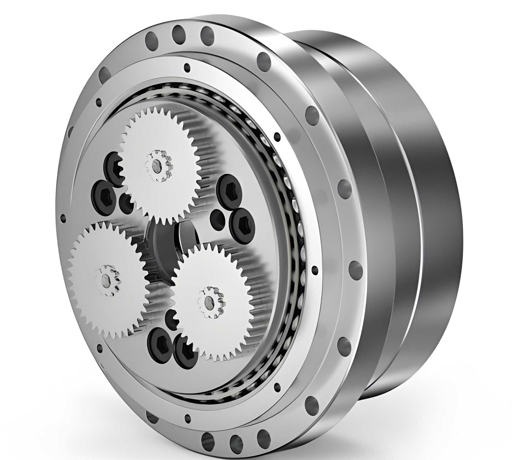
The mathematical model is based on the d’Alembert principle, where the forces acting on each component—such as the sun gear, planet gears, crankshafts, cycloid discs, pin wheel, and planet carrier—are balanced considering their masses, moments of inertia, and the stiffness of supports and meshing contacts. These stiffness values are represented by springs in the mechanical model, as illustrated in the figure above. The model incorporates various error factors as input parameters, allowing for the simulation of real-world imperfections. The dynamic equations of motion are derived as a set of nonlinear differential equations, which can be solved using numerical methods like the nonlinear Newmark method. From the solution, the actual rotation angle of the output shaft, denoted as $$θ_{ca}$$, is obtained at any time instant. The theoretical rotation angle of the output planet carrier, $$θ_c$$, is given by the input sun gear rotation angle $$θ_s$$ divided by the transmission ratio $$N$$:
$$θ_c = \frac{θ_s}{N}$$
The instantaneous transmission error $$θ_{er}$$ is then defined as the deviation between the actual and theoretical angles:
$$θ_{er} = θ_{ca} – θ_c$$
To quantify the overall transmission accuracy, I define the system’s transmission precision $$Δθ$$ as the maximum absolute value of the instantaneous transmission error over a stable operational cycle:
$$Δθ = \max\{ |θ_{er}| \}$$
This metric serves as the objective function in the sensitivity analysis, where I investigate how changes in error parameters affect $$Δθ$$. The transmission accuracy of the rotary vector reducer is thus a function of multiple error variables, and understanding their individual and combined impacts is crucial for improvement.
To perform the sensitivity analysis, I adopt a numerical differentiation approach, as the objective function $$Δθ$$ cannot be expressed in a simple closed form but is derived from the numerical solution of the dynamical model. Let the vector of error factors be represented as $$\mathbf{x} = [x_1, x_2, \dots, x_k]$$, where each $$x_i$$ corresponds to a specific error type, such as machining tolerances or assembly offsets. The transmission accuracy is then a function of these variables: $$f(\mathbf{x}) = Δθ(\mathbf{x})$$. The sensitivity of the transmission accuracy to each error factor is defined as the partial derivative of $$f$$ with respect to that variable:
$$S_i = \frac{\partial f}{\partial x_i} \quad \text{for} \quad i = 1, 2, \dots, k$$
In practice, since $$f$$ is only available through numerical computation, I approximate these partial derivatives using finite differences. Specifically, the forward difference quotient is employed:
$$S_i \approx \frac{f(\mathbf{x} + Δx_i \cdot \mathbf{e}_i) – f(\mathbf{x})}{Δx_i}$$
where $$\mathbf{e}_i$$ is the unit vector in the direction of the $$i$$-th error variable, and $$Δx_i$$ is a small perturbation. To enhance accuracy, especially when dealing with nonlinear effects, I use a five-point interpolation numerical differentiation method. This involves sampling the transmission accuracy over a range of error values—typically from 0 to 50 μm for consistency—and grouping the data points into sets of five. For each group, the Lagrange interpolation is applied to estimate the derivative at the central point. This process yields a sensitivity curve for each error combination, allowing for a detailed examination of how sensitivity varies with error magnitude. The resulting sensitivity values, expressed in arcseconds per micrometer (″/μm), provide a direct measure of the impact of each error factor on the transmission accuracy of the rotary vector reducer.
The error factors considered in this study are categorized into three main groups: (1) machining and assembly errors in the first-stage planetary gear system, (2) machining and assembly errors in the second-stage cycloid-pin gear system, and (3) bearing clearances throughout the rotary vector reducer. Each group comprises various combination modes, which define how errors are distributed among components. To organize this information, I present the error combination modes in tables below, summarizing their descriptions and the corresponding sensitivity results. These tables are essential for identifying which errors are most critical and how their combinations exacerbate or mitigate effects on transmission accuracy.
| Error Code | Description | Typical Range (μm) | Sensitivity (″/μm) |
|---|---|---|---|
| AS | Assembly error of the sun gear | 0–50 | < 0.1 |
| ES | Base circle eccentricity error of the sun gear | 0–50 | < 0.1 |
| EP | Base circle eccentricity error of the planet gears | 0–50 | < 0.1 |
As shown in Table 1, the errors in the first-stage planetary gear system—including sun gear assembly errors and base circle eccentricities of both sun and planet gears—have minimal impact on the transmission accuracy of the rotary vector reducer. Their sensitivity values are consistently below 0.1 ″/μm, indicating that these factors contribute negligibly to overall performance degradation. This is largely due to the inherent averaging effects in planetary gear trains, where multiple planet gears distribute loads and errors, reducing their influence on the output. Therefore, in the design and manufacturing of rotary vector reducers, focusing on the first-stage errors may not yield significant improvements in transmission accuracy.
In contrast, the second-stage cycloid-pin gear system exhibits a wide array of error combination modes that profoundly affect transmission accuracy. These errors are associated with the cycloid discs, pin wheel, crankshafts, and related assembly processes. Below, I detail these modes in separate tables, highlighting their specific characteristics and calculated sensitivity values. The sensitivity analysis reveals that the impact depends heavily on the phase relationships and symmetry of errors among components, underscoring the complexity of error propagation in rotary vector reducers.
| Error Code | Description | Phase Relationship | Sensitivity (″/μm) |
|---|---|---|---|
| RD-1 | Tooth groove deviation (1st harmonic) on one cycloid disc | Single disc | 1.153 |
| RD-2 | Tooth groove deviation (1st harmonic) on both cycloid discs, in-phase | Same direction | 0.451 |
| RD-3 | Tooth groove deviation (1st harmonic) on both cycloid discs, anti-phase | Opposite direction (180° apart) | 2.312 |
| RD-4 | Tooth groove deviation (2nd harmonic) on one cycloid disc | Single disc | 1.518 |
| RD-5 | Tooth groove deviation (2nd harmonic) on both cycloid discs, in-phase | Same direction | 1.058 |
| RD-6 | Tooth groove deviation (2nd harmonic) on both cycloid discs, anti-phase | Opposite direction (180° apart) | 0.182 |
| APD-1 | Cumulative pitch error (1st harmonic) on one cycloid disc | Single disc | 0.644 |
| APD-2 | Cumulative pitch error (1st harmonic) on both cycloid discs, in-phase | Same direction | 0.497 |
| APD-3 | Cumulative pitch error (1st harmonic) on both cycloid discs, anti-phase | Opposite direction (180° apart) | 1.251 |
| APD-4 | Cumulative pitch error (2nd harmonic) on one cycloid disc | Single disc | 0.843 |
| APD-5 | Cumulative pitch error (2nd harmonic) on both cycloid discs, in-phase | Same direction | 0.531 |
| APD-6 | Cumulative pitch error (2nd harmonic) on both cycloid discs, anti-phase | Opposite direction (180° apart) | 0.188 |
The data in Table 2 demonstrate that errors on cycloid discs in rotary vector reducers are highly sensitive to their harmonic components and phase relationships. For first-harmonic errors (e.g., RD-1 to RD-3 and APD-1 to APD-3), anti-phase combinations between the two cycloid discs—which are typically installed 180° apart—result in higher sensitivity because the errors add up constructively. In contrast, in-phase combinations lead to lower sensitivity as errors tend to cancel out. For second-harmonic errors (e.g., RD-4 to RD-6 and APD-4 to APD-6), the opposite trend is observed: in-phase combinations cause greater sensitivity, while anti-phase combinations reduce it. This behavior can be explained by the meshing dynamics of the cycloid-pin system, where harmonic errors interact differently due to the geometry of engagement. For instance, the transmission error $$θ_{er}$$ might be modeled as a function of these errors, such as $$θ_{er} = \sum_{n} (A_n \cos(n\phi) + B_n \sin(n\phi))$$, where $$n$$ is the harmonic order and $$\phi$$ is the rotation angle. The sensitivity analysis quantifies how coefficients like $$A_n$$ and $$B_n$$ vary with error magnitudes, providing a basis for tolerance allocation in manufacturing rotary vector reducers.
| Error Code | Description | Phase/Symmetry Condition | Sensitivity (″/μm) |
|---|---|---|---|
| EDH-1 | Eccentricity error of crankshaft holes on one cycloid disc | Single disc | 1.672 |
| EDH-3 | Eccentricity error of crankshaft holes on both cycloid discs, anti-phase | Opposite direction (180° apart) | 3.344 |
| EDH-6 | Eccentricity error of crankshaft holes in radial direction | Radial alignment | 0.549 |
| EDH-8 | Eccentricity error of crankshaft holes on both cycloid discs, anti-phase (variant) | Opposite direction | 1.101 |
| RI-1 | Tooth groove deviation (1st harmonic) of the pin wheel | Single harmonic | 0.535 |
| RI-2 | Tooth groove deviation (2nd harmonic) of the pin wheel | Second harmonic | 1.035 |
| API-1 | Cumulative pitch error (1st harmonic) of the pin wheel | Single harmonic | 0.345 |
| API-2 | Cumulative pitch error (2nd harmonic) of the pin wheel | Second harmonic | 0.635 |
Table 3 highlights errors related to the crankshaft holes on cycloid discs and the pin wheel in rotary vector reducers. The eccentricity errors of crankshaft holes show high sensitivity when they are in anti-phase between the two cycloid discs (e.g., EDH-3 with 3.344 ″/μm), suggesting that simultaneous machining of these holes to ensure in-phase alignment can significantly improve transmission accuracy. Radial-direction errors (e.g., EDH-6) have lower sensitivity, as they may not directly affect the meshing geometry. For the pin wheel, second-harmonic errors (RI-2 and API-2) exhibit higher sensitivity than first-harmonic ones, which aligns with the earlier observation for cycloid discs. This is because the two cycloid discs mesh with the same pin wheel but are 180° out of phase, causing first-harmonic errors to cancel out, whereas second-harmonic errors amplify. Mathematically, if the pin wheel error is represented as $$E_p(\theta) = \sum_{m} C_m \cos(m\theta + \psi_m)$$, then the net effect on transmission error depends on the phase difference between the cycloid discs, leading to sensitivity terms like $$S \propto |C_m| \cdot |1 – e^{im\pi}|$$ for harmonic order $$m$$. This underscores the importance of controlling higher-order harmonics in the pin wheel of rotary vector reducers.
| Error Code | Description | Symmetry Condition | Sensitivity (″/μm) |
|---|---|---|---|
| EC-1 | Eccentricity error of eccentric cams, asymmetric on two cycloid discs | Asymmetric | 0.786 |
| EC-3 | Eccentricity error of eccentric cams, anti-phase on two cycloid discs | Anti-phase | 1.566 |
| EC-7 | Eccentricity error of eccentric cams, partial asymmetry | Asymmetric | 0.770 |
| EC-8 | Eccentricity error of eccentric cams, mixed asymmetry | Asymmetric | 0.802 |
| EC-9 | Eccentricity error of eccentric cams, complex asymmetry | Asymmetric | 1.371 |
| ECH-1 | Eccentricity error of crankshaft holes on planet carrier | — | < 0.1 |
| ECH-2 | Assembly error of planet carrier | — | < 0.1 |
| ECH-3 | Eccentricity error of planet carrier | — | < 0.1 |
| AC | Assembly error of crankshafts | — | < 0.1 |
In Table 4, the error combination modes for eccentric cams and the planet carrier in rotary vector reducers are summarized. The eccentricity errors of eccentric cams show moderate to high sensitivity, especially in anti-phase or asymmetric configurations (e.g., EC-3 and EC-9). This indicates that uniform errors across all cams (e.g., all in the same direction) are less detrimental, while asymmetric distributions can lead to uneven loading and increased transmission inaccuracies. The planet carrier-related errors (ECH-1 to ECH-3 and AC) have negligible sensitivity, similar to first-stage errors, because the carrier primarily serves as a support structure without direct involvement in the precision meshing process. Thus, in the design of rotary vector reducers, emphasis should be placed on ensuring symmetry and phase alignment of eccentric cams to mitigate their impact on transmission accuracy.
Beyond machining and assembly errors, bearing clearances play a pivotal role in the performance of rotary vector reducers. These clearances introduce additional degrees of freedom and nonlinearities into the system, often exacerbating transmission errors. The following tables detail the combination modes for bearing clearances and their sensitivity values, revealing that they are among the most influential factors affecting transmission accuracy.
| Error Code | Description | Location | Sensitivity (″/μm) |
|---|---|---|---|
| CDC-1 | Bearing clearance between cycloid discs and crankshafts | Cycloid disc-crankshaft interface | 1.846 |
| CDC-2 | Bearing clearance, variant distribution | Cycloid disc-crankshaft interface | 2.103 |
| CDC-3 | Bearing clearance, asymmetric on discs | Cycloid disc-crankshaft interface | 1.646 |
| CDC-4 | Bearing clearance, uniform on all crankshafts | Cycloid disc-crankshaft interface | 2.333 |
| CDC-5 | Bearing clearance, maximum asymmetry | Cycloid disc-crankshaft interface | 2.776 |
| CDC-6 | Bearing clearance, partial uniformity | Cycloid disc-crankshaft interface | 2.459 |
| CDC-7 | Bearing clearance, mixed conditions | Cycloid disc-crankshaft interface | 1.997 |
| CDC-8 | Bearing clearance, random distribution | Cycloid disc-crankshaft interface | 2.034 |
| CDC-9 | Bearing clearance, minimized but present | Cycloid disc-crankshaft interface | 1.472 |
| CCC-1 | Bearing clearance between planet carrier and crankshafts | Planet carrier-crankshaft interface | 2.408 |
| CCC-2 | Bearing clearance, variant on carrier | Planet carrier-crankshaft interface | 2.876 |
| CCC-3 | Bearing clearance, asymmetric on carrier | Planet carrier-crankshaft interface | 2.354 |
| CCA | Bearing clearance between planet carrier and frame | Planet carrier-frame interface | < 0.1 |
As evident from Table 5, bearing clearances in rotary vector reducers have substantial sensitivity values, often exceeding 2 ″/μm. The clearances between the planet carrier and crankshafts (CCC series) show the highest sensitivity, up to 2.876 ″/μm, indicating that this interface is critical for transmission accuracy. This is because these clearances directly affect the alignment and motion of the crankshafts, which drive the cycloid discs. Similarly, clearances between cycloid discs and crankshafts (CDC series) also exhibit high sensitivity, with values ranging from 1.472 to 2.776 ″/μm. In contrast, the clearance between the planet carrier and the frame (CCA) has negligible impact, as it does not influence the precision meshing directly. The high sensitivity of bearing clearances can be attributed to their role in introducing backlash and nonlinear stiffness, which amplify transmission errors. For instance, the force transmission in the presence of clearance can be modeled as a piecewise function: $$F = k(\delta – c) \text{ for } \delta > c$$, where $$k$$ is stiffness, $$\delta$$ is displacement, and $$c$$ is clearance. This nonlinearity leads to discontinuous dynamics, increasing the sensitivity of transmission accuracy to clearance variations. Therefore, in the design of rotary vector reducers, minimizing or eliminating these clearances through preload or precision bearings is essential for achieving high transmission accuracy.
To synthesize the findings, I present a consolidated sensitivity summary in Table 6, which ranks the error combination modes based on their average sensitivity values. This table serves as a quick reference for designers and manufacturers of rotary vector reducers, highlighting the most critical areas for attention.
| Rank | Error Category | Representative Error Code | Average Sensitivity (″/μm) | Key Insight |
|---|---|---|---|---|
| 1 | Bearing Clearances (Planet Carrier-Crankshaft) | CCC-2 | 2.876 | Highest impact; minimize clearances |
| 2 | Bearing Clearances (Cycloid Disc-Crankshaft) | CDC-5 | 2.776 | Critical interface; ensure uniformity |
| 3 | Cycloid Disc Errors (Anti-phase 1st Harmonic) | RD-3 | 2.312 | Phase control vital; avoid anti-phase |
| 4 | Crankshaft Hole Eccentricities (Anti-phase) | EDH-3 | 3.344 | Simultaneous machining recommended |
| 5 | Eccentric Cam Errors (Anti-phase) | EC-3 | 1.566 | Symmetry reduces sensitivity |
| 6 | Pin Wheel Errors (2nd Harmonic) | RI-2 | 1.035 | Control higher harmonics |
| 7 | First-Stage Errors | AS, ES, EP | < 0.1 | Negligible impact |
| 8 | Planet Carrier Errors | ECH series | < 0.1 | Minimal influence |
The sensitivity analysis leads to several overarching conclusions regarding the transmission accuracy of rotary vector reducers. First, the second-stage cycloid-pin gear system is the primary contributor to transmission inaccuracies, whereas the first-stage planetary gear system has a negligible effect. Within the second stage, the impact of errors is highly dependent on their combination modes, particularly the phase relationships and harmonic contents. Anti-phase combinations for first-harmonic errors on cycloid discs and crankshaft holes significantly increase sensitivity, while for second-harmonic errors, in-phase combinations are more detrimental. This underscores the importance of precision in the manufacturing and assembly of cycloid discs and pin wheels, with an emphasis on controlling harmonic distortions and ensuring proper phase alignment. Second, bearing clearances, especially at the planet carrier-crankshaft and cycloid disc-crankshaft interfaces, exhibit the highest sensitivity values, making them the most critical factors for transmission accuracy. Reducing these clearances through design improvements, such as using preloaded bearings or tighter tolerances, can yield substantial gains in performance. Third, errors related to eccentric cams and the planet carrier have moderate to low sensitivity, but asymmetry should be avoided to prevent localized stress and error amplification. Mathematical models, such as those incorporating nonlinear stiffness and error propagation equations, support these findings by showing how small changes in error parameters lead to disproportionate changes in transmission error. For example, the sensitivity $$S_i$$ can be linked to the system’s Jacobian matrix, where $$S_i = \frac{\partial Δθ}{\partial x_i} = \mathbf{J}^{-1} \cdot \frac{\partial \mathbf{F}}{\partial x_i}$$, with $$\mathbf{F}$$ representing the dynamic forces. This theoretical framework validates the numerical results and provides a basis for further optimization.
In practical terms, this study offers actionable guidelines for the design and manufacturing of high-precision rotary vector reducers. Designers should prioritize minimizing bearing clearances in critical interfaces, perhaps by specifying interference fits or advanced sealing techniques. Manufacturers should focus on controlling the phase relationships of errors on cycloid discs and crankshaft holes, potentially through synchronized machining processes. Additionally, quality control measures should target the reduction of second-harmonic errors in the pin wheel and cycloid discs, as these have a pronounced effect on transmission accuracy. By integrating these insights, the performance of rotary vector reducers can be enhanced, meeting the demands of applications requiring ultra-high precision, such as surgical robots or satellite positioning systems. Future work could explore the combined effects of multiple error types using advanced sensitivity analysis methods, such as global sensitivity analysis or machine learning techniques, to further refine the understanding of error propagation in these complex systems. Ultimately, the goal is to achieve a balance between manufacturing feasibility and performance, ensuring that rotary vector reducers remain reliable and accurate components in the ever-evolving landscape of precision engineering.