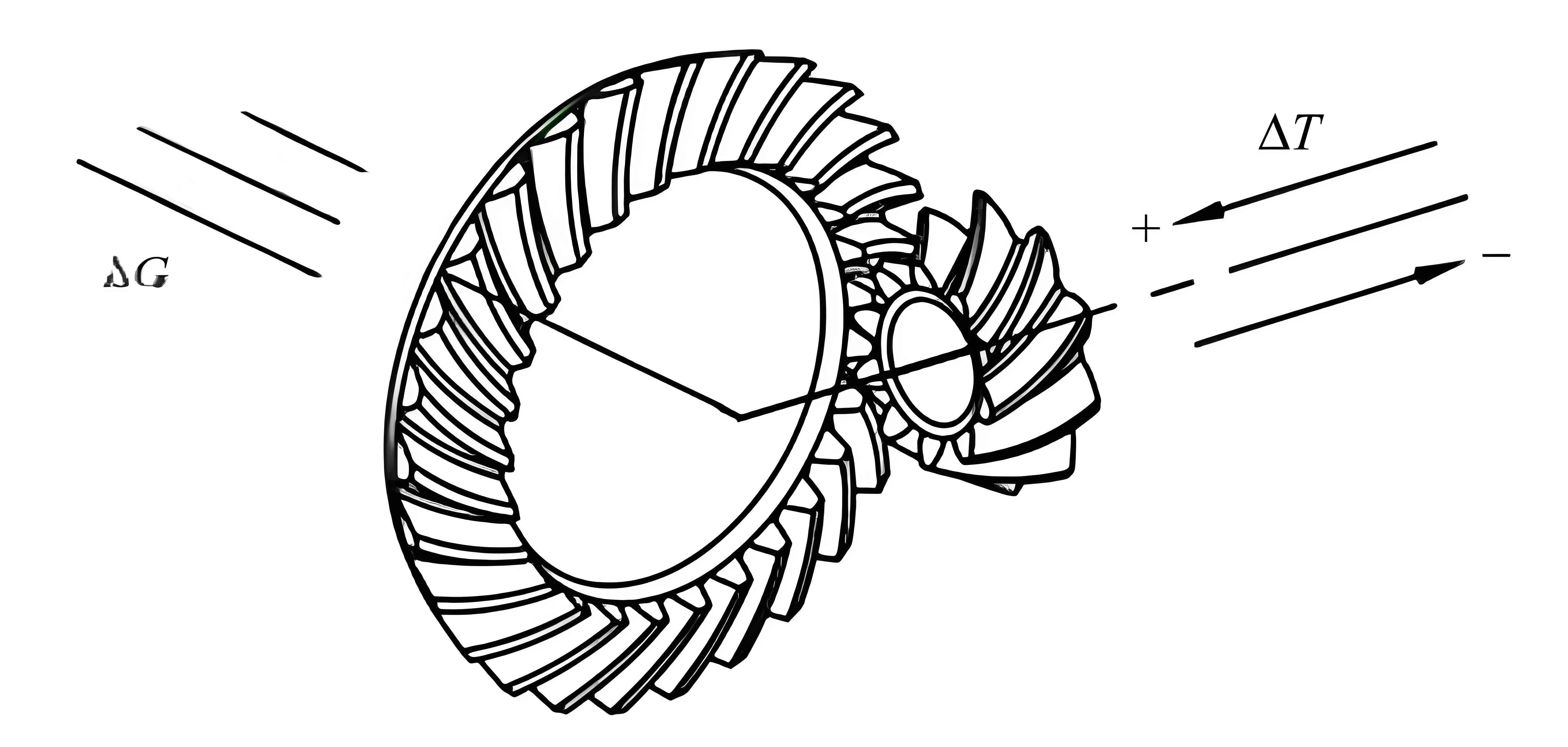
Spiral bevel gears are critical components in automotive, aerospace, and heavy machinery industries due to their high load-bearing capacity, efficiency, and compact design. However, achieving precision in their tooth surfaces remains a significant challenge, as machining deviations directly impact performance and longevity. This study focuses on analyzing the sensitivity of spiral bevel gear tooth surface deviations to geometric errors in computer numerical control (CNC) machine tools. By comparing local and global sensitivity analysis methods, we identify key geometric errors and establish guidelines for selecting appropriate sensitivity analysis frameworks.

1. Sensitivity Analysis Methods
Sensitivity analysis quantifies how variations in input parameters (e.g., machine tool errors) affect output metrics (e.g., tooth surface deviations). Two primary approaches are explored:
1.1 Local Sensitivity Analysis
Local sensitivity analysis evaluates the effect of perturbing a single input parameter while keeping others constant. The sensitivity coefficient SiSi is calculated as:Si=∂K∂xi⋅xiK,Si=∂xi∂K⋅Kxi,
where KK is the output metric (total tooth surface deviation) and xixi is the ii-th input parameter. This method is computationally efficient but limited to linear or weakly nonlinear models.
Key Steps:
- Define nominal values for all inputs.
- Perturb one parameter at a time.
- Compute sensitivity coefficients via finite differences.
1.2 Sobol Global Sensitivity Analysis
The Sobol method, a variance-based global approach, accounts for parameter interactions and nonlinear effects. The total variance DD of the output is decomposed into contributions from individual parameters and their interactions:D=∑i=1nDi+∑1≤i<j≤nDij+⋯+D1,2,…,n.D=i=1∑nDi+1≤i<j≤n∑Dij+⋯+D1,2,…,n.
Sensitivity indices are computed as:Si=DiD,Sij=DijD,andSitotal=Si+∑j≠iSij+⋯ .Si=DDi,Sij=DDij,andSitotal=Si+j=i∑Sij+⋯.
Monte Carlo sampling generates input matrices EE and FF, and indices are approximated using:Si≈1N∑k=1Nf(Fk)(f(Ek(i))−f(Ek)),Si≈N1k=1∑Nf(Fk)(f(Ek(i))−f(Ek)),Sitotal≈12N∑k=1N(f(Ek)−f(Ek(i)))2,Sitotal≈2N1k=1∑N(f(Ek)−f(Ek(i)))2,
where Ek(i)Ek(i) replaces the ii-th column of EE with that of FF.
2. Machine Tool Geometric Errors
A 5-axis CNC machine tool for spiral bevel gear machining involves 30 geometric errors across linear and angular axes (Table 1).
Table 1: Geometric errors in a 5-axis CNC machine tool
| Axis | Linear Errors (δδ) | Angular Errors (ϵϵ) |
|---|---|---|
| X | δxX,δyX,δzXδxX,δyX,δzX | ϵαX,ϵβX,ϵγXϵαX,ϵβX,ϵγX |
| Y | δxY,δyY,δzYδxY,δyY,δzY | ϵαY,ϵβY,ϵγYϵαY,ϵβY,ϵγY |
| Z | δxZ,δyZ,δzZδxZ,δyZ,δzZ | ϵαZ,ϵβZ,ϵγZϵαZ,ϵβZ,ϵγZ |
| A | δxA,δyA,δzAδxA,δyA,δzA | ϵαA,ϵβA,ϵγAϵαA,ϵβA,ϵγA |
| B | δxB,δyB,δzBδxB,δyB,δzB | ϵαB,ϵβB,ϵγBϵαB,ϵβB,ϵγB |
3. Tooth Surface Deviation Model
The theoretical tooth surface rsrs is derived from the homogeneous transformation matrices of machine axes:rs=MX⋅MY⋅MZ⋅MA⋅MB⋅rt(u,θ),rs=MX⋅MY⋅MZ⋅MA⋅MB⋅rt(u,θ),
where rt(u,θ)rt(u,θ) represents the tool surface. Incorporating geometric errors modifies the surface to:rs′=MX′⋅MY′⋅MZ′⋅MA′⋅MB′⋅rt(u,θ).rs′=MX′⋅MY′⋅MZ′⋅MA′⋅MB′⋅rt(u,θ).
The total deviation KK is computed as:K=∑i=1135∣rs(i)−rs′(i)∣,K=i=1∑135∣rs(i)−rs′(i)∣,
where ii indexes 135 discrete points on the tooth surface.
4. Case Study and Results
A spiral bevel gear with parameters in Table 2 was analyzed.
Table 2: Geometric and machining parameters
| Parameter | Value |
|---|---|
| Number of teeth (Z1Z1) | 18 |
| Module (mm) | 4.29 mm |
| Face width (ww) | 45 mm |
| Spiral angle (ββ) | 35° |
4.1 Local Sensitivity Results
Linear errors in the yy-direction (e.g., δyX,δyYδyX,δyY) exhibited the highest sensitivity coefficients (Figure 1). Angular errors ϵγX,ϵγYϵγX,ϵγY, and ϵγZϵγZ also significantly impacted deviations.
Figure 1: Local sensitivity coefficients for linear errors
| Error ID | Sensitivity Coefficient |
|---|---|
| δyXδyX | 0.45 |
| δyYδyY | 0.38 |
| δyZδyZ | 0.29 |
4.2 Sobol Global Sensitivity Results
Global analysis highlighted interactions between errors. For example, increasing δyYδyY’s range from 0–10 μm to 0–20 μm raised its total sensitivity index from 0.023 to 0.154 (Figure 2).
Figure 2: Global sensitivity indices after parameter range adjustment
| Error ID | Original SitotalSitotal | Adjusted SitotalSitotal |
|---|---|---|
| δyYδyY | 0.023 | 0.154 |
5. Comparative Analysis
- Local Sensitivity:
- Pros: Low computational cost, suitable for linear models.
- Cons: Ignores parameter interactions and nonlinearities.
- Global Sensitivity:
- Pros: Captures interactions and nonlinear effects.
- Cons: Computationally intensive, requires large sample sizes.
Guidelines for Method Selection:
- Use local sensitivity when input distributions are unknown or similar, and nonlinearity is weak.
- Use global sensitivity for complex input distributions or high-accuracy nonlinear models.
6. Conclusion
This study demonstrates that spiral bevel gear tooth surface deviations are most sensitive to linear errors in the yy-direction and specific angular errors. While local sensitivity analysis provides quick insights, Sobol’s global method offers a comprehensive view of parameter interactions. The findings guide the selection of sensitivity analysis frameworks for optimizing CNC machine tools, ultimately enhancing the precision of spiral bevel gears in critical applications.
