
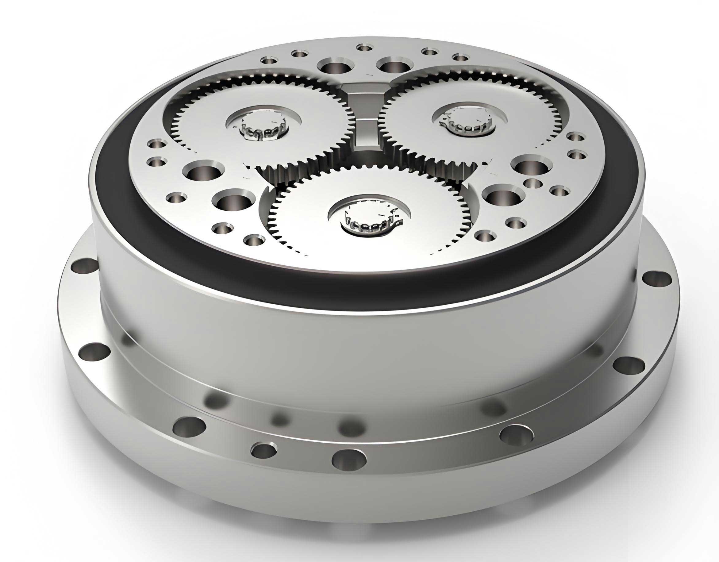
In the field of precision mechanical transmission, the rotary vector reducer, often abbreviated as RV reducer, has emerged as a pivotal component due to its exceptional performance characteristics. As a researcher focused on mechanical design and theory, I have extensively studied the dynamic behavior of these reducers, particularly how various errors influence their transmission accuracy. The rotary vector reducer combines a planetary gear stage with a cycloidal pin gear stage, offering advantages such as high reduction ratios, compact design, high stiffness, and excellent positional accuracy. These features make it indispensable in applications like industrial robots, CNC machine tools, textile machinery, and printing presses, where precise motion control is paramount. However, achieving and maintaining high transmission accuracy is challenging due to the cumulative effects of manufacturing imperfections, assembly errors, and internal clearances. This article presents a comprehensive investigation into the sensitivity of transmission accuracy to these error sources in a rotary vector reducer, employing a nonlinear dynamic model and numerical techniques to identify the most critical factors.
The core objective of this work is to develop a methodology that quantifies the impact of individual errors on the overall transmission error of a rotary vector reducer. Transmission accuracy is typically defined as the deviation between the theoretical output rotation and the actual output rotation under load. In dynamic conditions, this error fluctuates due to time-varying meshing forces, stiffness variations, and error excitations. A holistic approach requires considering all significant error types: machining errors like eccentricities and tooth profile deviations, assembly errors such as misalignments, and operational clearances in bearings and joints. By establishing a detailed dynamic model and performing a sensitivity analysis, we can pinpoint which errors contribute most significantly to transmission inaccuracy. This knowledge is crucial for guiding the design, manufacturing, and assembly processes of high-precision rotary vector reducers, enabling targeted tolerance control and potential error compensation strategies.
The foundation of our analysis is a nonlinear dynamic model of the rotary vector reducer system. The model is derived using D’Alembert’s principle, which balances inertial forces with applied forces and elastic reactions. To represent the system’s compliance, we model stiffnesses using spring elements: the meshing stiffness between the sun gear and planet gears ($k_{spi}$), the bearing support stiffness between the crank shaft and the cycloid gear’s bore ($k_{dcji}$), the bearing stiffness between the crank shaft and the planet carrier’s bore ($k_{bi}$), the bearing support stiffness between the planet carrier and the housing ($k_{ca}$), the meshing stiffness between the cycloid gear teeth and the pin teeth ($k_{djk}$), and the support stiffness of the sun gear shaft ($k_s$). These stiffness values are not constant; for contact-based stiffnesses like $k_{dcji}$, $k_{bi}$, $k_{ca}$, and $k_{djk}$, we use the Palmgren formula which depends on material properties, contact geometry, and load. For instance, the bearing stiffness can be expressed as $k = C P^{0.1}$, where $C$ is a constant and $P$ is the load. The gear meshing stiffness $k_{spi}$ is derived from tooth bending deformation theory, and $k_s$ is determined from the sun gear shaft’s bending deflection.
The dynamic state of each component is described by small displacements from their ideal positions. We define: $X_s, Y_s$ for the sun gear’s translational displacements; $X_{pi}, Y_{pi}$ and $\theta_{pi} – \theta_p$ (for $i=1,2,3$) for the planet gear and crank shaft’s translational and rotational displacements (where $\theta_p$ is the theoretical planet rotation and $\theta_{pi}$ is the actual); $\eta_{dj}$, $\theta_{dj} – \theta_c$, and $\theta_{doj} – \theta_p$ (for $j=1,2$) for the cycloid gear’s radial displacement, relative rotation, and revolution displacement ($\theta_c$ is the theoretical carrier angle, $\theta_{dj}$ is the cycloid gear’s actual rotation, $\theta_{doj}$ is its revolution angle); and $X_{ca}, Y_{ca}, \theta_{ca} – \theta_c$ for the planet carrier’s displacements. The total dynamic transmission error $\Delta \theta_{ca}$ is then $\theta_{ca} – \theta_c$, where $\theta_{ca}$ is the actual output carrier angle obtained from solving the equations of motion.
To incorporate imperfections, we model a wide array of error sources. Each error is characterized by a magnitude and often a phase angle. For the sun gear: base circle eccentricity $(E_s, \beta_s)$ and assembly error $(A_s, \gamma_s)$. For planet gears: base circle eccentricity $(E_{pi}, \beta_{pi})$. For the crank shaft: eccentricity of the cam lobe $(E_{cji}, \beta_{cji})$. For the planet carrier: eccentricity of the crank pin holes $(E_{cai}, \beta_{cai})$, assembly error $(A_c, \gamma_c)$, bearing clearance at the crank pin holes $\delta_{xi}$, and bearing clearance between carrier and housing $\delta_{ca}$. For the pin gear: tooth space deviation $R_{jk}$ and cumulative pitch deviation $AP_{jk}$. For the cycloid gear: tooth space deviation $R_{djk}$, cumulative pitch deviation $AP_{djk}$, eccentricity of the crank shaft bore $(E_{hji}, \beta_{hji})$, and associated bearing clearance $\delta_{bji}$. For the pins themselves: diameter error $\delta_{jk}$ and radius error of the pin tip profile $\delta_{thjk}$. These errors are introduced as perturbations in the kinematic relationships and force equations.
The forces at mating interfaces and supports are functions of these errors, clearances, and the dynamic displacements. The general approach is to express the relative deflection at a contact point and multiply by the appropriate stiffness. For example:
1. Sun gear support forces:
$$ P_{sx} = k_s (X_s – A_s \cos \gamma_s), \quad P_{sy} = k_s (Y_s – A_s \sin \gamma_s) $$
2. Sun-planet gear meshing force:
$$ P_{spi} = k_{spi} \left[ X_s \cos A_i + Y_s \sin A_i – X_{pi} \cos A_i – Y_{pi} \sin A_i – R_{bp} (\theta_{pi} – \theta_p) + E_s \cos(\theta_s + \beta_s – A_i) – E_{pi} \cos(\beta_{pi} – \theta_p – A_i) \right] $$
where $A_i = \theta_c + \phi_i + \pi/2 – \alpha’$, $\alpha’$ is the operating pressure angle, $R_{bp}$ is the base radius of the planet gear, and $\theta_s$ is the sun gear rotation angle.
3. Cycloid gear-crank shaft contact forces (in X and Y directions):
$$ P_{dcjix} = k_{dcji} \left[ X_{pi} – R_e \theta_{pi} \sin(\theta_p + \psi_j) – \eta_{dj} \cos(\theta_p + \psi_j) + R_{dc} (\theta_{dj} – \theta_c) \sin(\theta_c + \phi_i) + R_e \theta_{doj} \sin(\theta_p + \psi_j) – E_{hji} \cos(\theta_c + \phi_i + \beta_{hji}) + E_{cji} \cos(\theta_p + \psi_j + \beta_{cji}) \pm \delta_{bji} \right] $$
$$ P_{dcjiy} = k_{dcji} \left[ Y_{pi} – R_e \theta_{pi} \cos(\theta_p + \psi_j) + \eta_{dj} \sin(\theta_p + \psi_j) + R_{dc} (\theta_{dj} – \theta_c) \cos(\theta_c + \phi_i) + R_e \theta_{doj} \cos(\theta_p + \psi_j) – E_{hji} \sin(\theta_c + \phi_i + \beta_{hji}) + E_{cji} \sin(\theta_p + \psi_j + \beta_{cji}) \pm \delta_{bji} \right] $$
where $R_e$ is the eccentricity of the cycloid gear, $R_{dc}$ is the center distance in the first stage, and $\psi_j$, $\phi_i$ are angular position indices. The $\pm$ sign for clearance $\delta_{bji}$ is determined by the direction of contact separation.
4. Cycloid gear-pin tooth meshing force:
$$ P_{dijk} = k_{djk} \left[ \eta_{dj} \cos \alpha_{jk} – R_d (\theta_{dj} – \theta_c) \sin \alpha_{jk} + R_e (\theta_{doj} – \theta_p) \sin \alpha_{jk} – R_{jk} \cos(\alpha_{jk} – \phi_{ijk}) – AP_{jk} \sin(\alpha_{jk} – \phi_{ijk}) + R_{djk} \cos(\alpha_{jk} – \phi_{djk}) + AP_{djk} \sin(\alpha_{jk} – \phi_{djk}) – \delta_{jk} – \delta_{thjk} \right] $$
Here, $R_d$ is the pitch radius of the cycloid gear, $\alpha_{jk}$ is the angle defining the contact position, and $\phi_{ijk}$, $\phi_{djk}$ are phase angles related to tooth indexing.
5. Planet carrier-crank shaft contact forces:
$$ P_{ocix} = k_{bi} \left[ X_{pi} + R_{dc} (\theta_{ca} – \theta_c) \sin(\theta_c + \phi_i) – X_{ca} – E_{cai} \cos(\theta_c + \phi_i + \beta_{cai}) \pm \delta_{xi} \right] $$
$$ P_{ociy} = k_{bi} \left[ Y_{pi} – R_{dc} (\theta_{ca} – \theta_c) \cos(\theta_c + \phi_i) – Y_{ca} – E_{cai} \sin(\theta_c + \phi_i + \beta_{cai}) \pm \delta_{Yi} \right] $$
6. Planet carrier housing support forces:
$$ P_{cax} = k_{ca} (X_{ca} – A_c \cos \gamma_c \pm \delta_{ca}), \quad P_{cay} = k_{ca} (Y_{ca} – A_c \sin \gamma_c \pm \delta_{ca}) $$
Applying D’Alembert’s principle to each component (sun gear, planet gears, crank shafts, cycloid gears, planet carrier) yields a set of coupled nonlinear differential equations. The nonlinearity arises primarily from the piecewise nature of contact forces due to clearances (sign changes) and the load-dependent stiffness. We assume the input sun gear rotates at a constant speed, and neglect friction for simplicity. The system is solved for the dynamic displacements over time using a numerical integration scheme suitable for nonlinear systems, such as the Newmark-beta method. From the solution, we extract the actual output angle $\theta_{ca}(t)$ and compute the instantaneous transmission error $\Delta \theta_{ca}(t) = \theta_{ca}(t) – \theta_c(t)$. The overall transmission accuracy metric, denoted $\Delta \theta_{er}$, is defined as the maximum absolute transmission error over one full output revolution under steady-state operation:
$$ \Delta \theta_{er} = \max_{t \in T} | \Delta \theta_{ca}(t) | $$
where $T$ corresponds to one output revolution cycle.
To assess the influence of each error parameter, we perform a sensitivity analysis. Let the vector of error parameters be $\mathbf{X} = (x_1, x_2, \dots, x_k)^T$, where each $x_i$ represents a specific error magnitude (e.g., $E_s$, $A_c$, $\delta_{bji}$, etc.). The transmission accuracy $\Delta \theta_{er}$ is a function of these parameters: $\Delta \theta_{er} = f(\mathbf{X})$. The sensitivity vector $\mathbf{S}$ is the gradient of this function:
$$ \mathbf{S} = \nabla f = \left( \frac{\partial f}{\partial x_1}, \frac{\partial f}{\partial x_2}, \dots, \frac{\partial f}{\partial x_k} \right)^T $$
Each component $S_i = \partial f / \partial x_i$ represents the sensitivity of transmission accuracy to error $x_i$. A positive $S_i$ indicates that increasing $x_i$ increases the transmission error (degrading accuracy), while a negative value suggests the opposite. The magnitude of $S_i$ indicates the degree of sensitivity; larger absolute values mean the transmission accuracy is more sensitive to variations in that error.
Since the function $f$ is complex and implicit via the dynamic solution, we compute sensitivities using a numerical differentiation method. Specifically, we employ the five-point stencil formula for numerical derivatives. For each parameter $x_i$, we perturb it around its nominal value while keeping all other parameters fixed. The perturbation range is typically ±10% of the nominal. We evaluate $f$ at five points within this range: $x_i – 2h$, $x_i – h$, $x_i$, $x_i + h$, $x_i + 2h$, where $h$ is a small step size. The derivative is then approximated as:
$$ S_i \approx \frac{-f(x_i + 2h) + 8f(x_i + h) – 8f(x_i – h) + f(x_i – 2h)}{12h} $$
This provides a robust estimate of the local sensitivity. By repeating this process for each error parameter, we rank them according to their impact on the transmission accuracy of the rotary vector reducer.
For a concrete example, we analyze an RV-80E type rotary vector reducer with a reduction ratio of 81. The major structural parameters are listed in the table below.
| Stage | Component | Parameter | Value |
|---|---|---|---|
| First Stage (Planetary) | Sun Gear | Module (mm) | 1.75 |
| Number of Teeth | 16 | ||
| Planet Gear | Number of Teeth | 32 | |
| Face Width (mm) | 7.0 | ||
| Pressure Angle (°) | 20 | ||
| Addendum Modification Coefficients | Sun: 0.519, Planet: -0.555 | ||
| Second Stage (Cycloidal) | Cycloid Gear | Number of Teeth | 39 |
| Face Width (mm) | 12 | ||
| Pin Gear | Number of Teeth (Pins) | 40 | |
| Face Width (mm) | 24 | ||
| Pin Circle Radius (mm) | 76.5 | ||
| Pin Radius (mm) | 3 | ||
| Eccentricity (mm) | 1.5 | ||
The stiffness values used in the dynamic model, calculated based on the formulas mentioned earlier, are summarized below. Note that some stiffnesses are load-dependent; the values here are representative for typical load conditions.
| Stiffness Symbol | Expression / Value | Description |
|---|---|---|
| $k_s$ | $1.23 \times 10^5$ | Sun gear shaft support stiffness |
| $k_{spi}$ | $1.58 \times 10^5$ | Sun-planet gear meshing stiffness |
| $k_{dcji}$ | $1.93 \times 10^5 \, P_{dcji}^{0.1}$ | Crank shaft-cycloid gear bearing stiffness |
| $k_{bi}$ | $2.27 \times 10^5 \, P_{oci}^{0.1}$ | Crank shaft-planet carrier bearing stiffness |
| $k_{ca}$ | $2.15 \times 10^5 \, P_{ca}^{0.1}$ | Planet carrier-housing bearing stiffness |
| $k_{djk}$ | $1.93 \times 10^5 \, P_{dijk}^{0.1}$ | Cycloid gear-pin tooth meshing stiffness |
In the sensitivity study, we focus on error parameters that are known to have potential significant impact based on preliminary analyses. Errors like sun gear eccentricity and assembly error have been found to have minimal effect on the output transmission error of the rotary vector reducer, as the two-stage structure with symmetric planets tends to cancel out some first-stage errors. Therefore, we concentrate on errors in the second (cycloidal) stage and related assembly. For the analysis, each error magnitude is assigned a nominal value denoted by $e$, which we vary from 0.5 µm to 15 µm to observe sensitivity over a practical range. The specific errors considered are:
- Pin gear tooth space deviation: $R_{jk} = e \sin(2\theta_k)$
- Pin gear cumulative pitch deviation: $AP_{jk} = e \sin(2\theta_k)$
- Cycloid gear tooth space deviation: $R_{djk} = e \sin(2\theta_d)$
- Cycloid gear cumulative pitch deviation: $AP_{djk} = e \sin(2\theta_d)$
- Cycloid gear crank bore eccentricity: $(E_{hji}, \beta_{hji})$ with magnitudes $e$ and phases as per Table 3.
- Crank shaft cam lobe eccentricity: $(E_{cji}, \beta_{cji})$ with magnitudes $e$ and phases as per Table 4.
- Planet carrier crank hole eccentricity: $(E_{cai}, \beta_{cai})$ with magnitude $e$ and phases as per Table 5.
- Planet carrier assembly error: $(A_c, \gamma_c) = (e, 0^\circ)$
- Bearing clearance between planet carrier and housing: $\delta_{ca} = e$
- Bearing clearance between cycloid gear and crank shaft: $\delta_{bji}$ with values as per Table 6.
The phase angles for distributed errors (like eccentricities at different holes) are chosen to represent typical manufacturing variations. The tables below specify the phase angles (in degrees) for the multi-element errors. All magnitudes are set to $e$ for sensitivity computation.
| Cycloid Gear | Bore 1 Phase $\beta_{h1i}$ | Bore 2 Phase $\beta_{h2i}$ | Bore 3 Phase $\beta_{h3i}$ |
|---|---|---|---|
| Cycloid Gear 1 | 60° | 210° | 180° |
| Cycloid Gear 2 | 60° | 210° | 180° |
| Cycloid Gear | Cam 1 Phase $\beta_{c1i}$ | Cam 2 Phase $\beta_{c2i}$ | Cam 3 Phase $\beta_{c3i}$ |
|---|---|---|---|
| Cycloid Gear 1 | 90° | 0° | 270° |
| Cycloid Gear 2 | 270° | 180° | 90° |
| Hole 1 Phase | Hole 2 Phase | Hole 3 Phase |
|---|---|---|
| 60° | 300° | 180° |
| Cycloid Gear | Clearance at Bore 1 | Clearance at Bore 2 | Clearance at Bore 3 |
|---|---|---|---|
| Cycloid Gear 1 | $e$ | $e$ | 0 |
| Cycloid Gear 2 | $e$ | 0 | $e$ |
We compute the transmission accuracy $\Delta \theta_{er}$ for various values of $e$ across its range for each error type individually. The sensitivity $S_i$ for each error is then calculated using the five-point formula. The results reveal distinct sensitivity profiles. For conciseness, we describe key trends rather than listing all numerical values. The sensitivity curves for pin gear tooth space deviation and pin gear cumulative pitch deviation are similar in shape and magnitude. As shown in the conceptual graphs below, the sensitivity varies with the error magnitude $e$, indicating nonlinear interaction. At small $e$ (below ~2 µm), sensitivity is relatively lower; it increases to a peak in the mid-range (around 5-10 µm), and then may slightly decrease or plateau at higher values due to saturation effects in contact conditions. The absolute sensitivity values for these pin gear errors are among the highest observed, with $|S|$ often exceeding 2.5 (in units of µrad/µm, assuming output error in radians). This means a 1 µm increase in pin gear tooth space or pitch error can increase the peak transmission error by more than 2.5 µrad.
Similarly, the cycloid gear tooth space deviation and cumulative pitch deviation exhibit sensitivity curves nearly identical to those of the pin gear errors, with comparable magnitudes. This underscores the critical role of tooth profile accuracy in both the cycloid and pin gears for the overall transmission precision of the rotary vector reducer.
The sensitivity to crank shaft cam lobe eccentricity error is consistently high but shows less variation over the $e$ range, with values tightly clustered between 2.866 and 2.868. This indicates a nearly linear relationship: transmission error increases by about 2.867 µrad for every 1 µm increase in cam lobe eccentricity. This error directly affects the motion transfer between the crank shaft and the cycloid gear, making it a dominant factor.
The bearing clearance between the cycloid gear and the crank shaft ($\delta_{bji}$) also shows high sensitivity, ranging from 2.46 to 2.49. Clearances introduce nonlinear backlash, causing impact and lost motion, which significantly degrades transmission accuracy, especially under reversing loads or low torque.
In contrast, other errors exhibit much lower sensitivity. For instance, the cycloid gear crank bore eccentricity, planet carrier crank hole eccentricity, planet carrier assembly error, and the carrier-housing bearing clearance all have sensitivity magnitudes below 0.5, often much lower. Their influence on the output transmission error of the rotary vector reducer is minimal compared to the aforementioned critical errors. This can be attributed to error averaging across multiple planets and cycloid gears, as well as the force transmission paths that may not amplify these particular errors.
To illustrate the sensitivity ordering, we can summarize the findings qualitatively:
- High Sensitivity Errors (Primary Contributors):
- Pin gear tooth space deviation and cumulative pitch deviation.
- Cycloid gear tooth space deviation and cumulative pitch deviation.
- Crank shaft cam lobe eccentricity error.
- Bearing clearance between cycloid gear and crank shaft.
- Low Sensitivity Errors (Secondary/Minor Contributors):
- Cycloid gear crank bore eccentricity.
- Planet carrier crank hole eccentricity.
- Planet carrier assembly error.
- Carrier-housing bearing clearance.
- Sun gear and planet gear errors (not analyzed in detail here, but known to be low).
The nonlinear dynamic model also allows us to observe the time-domain waveform of the transmission error $\Delta \theta_{ca}(t)$. Under the influence of the high-sensitivity errors, the error signal exhibits periodic components at the meshing frequencies of both stages, modulated by the error excitation frequencies. For example, pin gear pitch errors introduce harmonics at the pin passing frequency. The presence of clearances causes abrupt jumps in the error curve near torque reversals. When multiple high-sensitivity errors coexist, their effects can combine constructively or destructively, but generally, the overall error increases.
In conclusion, this sensitivity analysis provides clear guidance for the precision manufacturing and assembly of rotary vector reducers. To achieve high transmission accuracy, manufacturers should prioritize tight tolerances and meticulous quality control on the tooth profiles of both the cycloid and pin gears. Specifically, tooth space deviations and cumulative pitch errors must be minimized. Furthermore, the machining of the crank shaft’s eccentric cam lobes requires high precision to control eccentricity errors. Lastly, managing the bearing clearance in the interface between the cycloid gear and the crank shaft is crucial; this might involve selecting high-precision bearings, preloading, or design adjustments to minimize backlash. Errors related to the planet carrier and some assembly aspects are less critical, allowing for slightly relaxed tolerances without significantly compromising the performance of the rotary vector reducer. This targeted approach optimizes cost and effort while ensuring the high performance demanded by advanced applications like robotics and precision machinery.
Future work could extend this model to include thermal effects, lubrication, and more detailed tooth contact analysis using finite element methods. Additionally, the sensitivity results could be used to develop active or passive error compensation techniques, further pushing the limits of accuracy for rotary vector reducers in next-generation industrial systems.