
Due to the large amount of three-dimensional finite element simulation calculation of helical gear, considering the factors such as computer resources, running time and cost, most scholars at home and abroad use local tooth model instead of full tooth model to improve the analysis efficiency. Therefore, aiming at the three tooth and five tooth models commonly used in the existing literature, the error of the simulation results of each local tooth model compared with the full tooth model in the dynamic and static contact simulation of helical gear is compared by using the three-dimensional finite element analysis method, which provides a reference for the contact simulation analysis and modeling of helical gear.
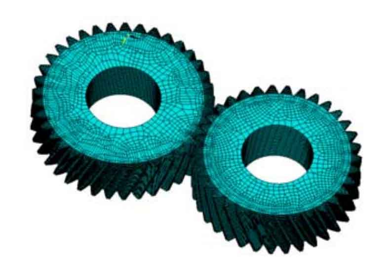
Taking a pair of helical gears in a transmission as an example, the local tooth model and full tooth model of helical gears are established by using the finite element analysis software ANSYS and ANSYS / LS-DYNA, as shown in Figure 1-5.


In the static analysis, the solid element is solid45 element, the contact element and target element are contact174 and target170 respectively, and the driving and driven gears define the same material properties. It is assumed that the driven wheel is stationary at the moment when the driving wheel engages with the driven wheel, so all its degrees of freedom are constrained and only the driving torque is applied to the driving wheel. The calculation results of contact stress of driving wheel in different types of local tooth models are shown in Figure 6-10. The table shows the relative error between the maximum equivalent stress of the driving wheel in the local tooth model and the maximum equivalent stress calculated by the full tooth model. It can be seen from figure 6-10 and table that in static analysis, the calculation results of local tooth model are greater than those of full tooth model; For the local tooth model with the same number of teeth, the calculation result of the model with rim is close to that of the full tooth model, and the error is small, while the error of the model without rim is large; For the local tooth model with different number of teeth, the calculation error of the five tooth model is smaller than that of the corresponding three tooth model; From the contact marks of helical gear meshing lines, the distribution trend of contact stress calculated by local tooth model is consistent with that of full tooth model. Because the loading area of the three tooth model without rim is small, the contact mark of the model is not clear, and the contact stress distribution of the helical gear is uneven. The contact mark of the other local tooth models is similar to that of the full tooth model, and the contact stress distribution of the helical gear is uniform.
| Maximum equivalent stress / PA | Local gear model error | |
| Full tooth | 0.12E10 | |
| Three teeth without rim | 0.199E10 | 65.8% |
| Three tooth belt rim | 0.149E10 | 24.2% |
| Five teeth without rim | 0.151E10 | 25.8% |
| Five tooth belt flange | 0.145E10 | 20.8% |


In the dynamic analysis, solid164 is selected as the solid element, the inner ring surface of the helical gear is defined as shell163 element, and its translation displacement and rotation freedom around the X and Y axes are constrained at the same time, and the helical gear rotates freely around the Z axis. The driving and driven gears define the same material properties. According to the actual working conditions of the helical gear, the angular speed is applied to the driving wheel and the resistance torque is applied to the driven wheel. Because there are many frames of dynamic contact simulation animation, they are not listed here one by one. In order to facilitate the comparison of stress results, the maximum equivalent stress in each frame of animation is the ordinate and the meshing time is the abscissa, which are programmed in MATLAB. The calculation results of the maximum equivalent contact stress of the driving wheel of the full tooth model and the local tooth model at different times during operation are shown in Figure 11-12. Figure 13 shows the comparison of the maximum equivalent contact stress curves of the driving wheel of the three tooth and five tooth local tooth model with rim and the full tooth model in a helical gear meshing cycle after the helical gear operates smoothly. It can be seen from Fig. 11 ~ 13 that during the movement of helical gear, due to the symmetry of helical gear, the change of maximum equivalent stress of helical gear after stable operation shows a certain regularity. Due to the small number of teeth, the regularity of local tooth model is not obvious, especially the model with few teeth without rim; For the local tooth model with the same number of teeth, at the end of the calculation, the number of teeth involved in the meshing of the local tooth model with rim is more than that of the local tooth model without rim, the meshing time is longer, the error of the calculation result is small, and it can more accurately reflect the dynamic meshing characteristics of helical gear; For the local tooth model with different number of teeth, the error of the three tooth belt flange model and the five tooth belt flange model is smaller than that of the full tooth model. Among them, the calculation error of the three tooth model is greater than that of the five tooth model. The calculation results of three tooth without flange model and five tooth without flange model have large errors compared with the full tooth model.


